AP05
Commissioning English
AP05 · Date 25.09.2018 · Art. No. 88847 · Mod. status 316/18
29
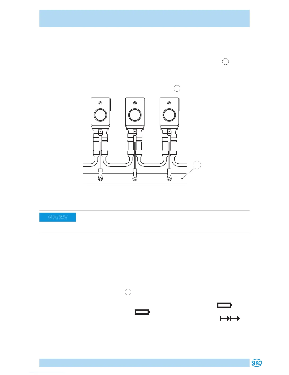
Earthing connection (PE)
For protection against interference, the screens of the signal lines and the
power line must be connected on both sides. Potential dierences cause
inadmissible currents on the screen. Install the PE connection
3
onto the
protective earth conductor potential between the plug connectors (see
Fig. 6). Use 6.3mm flat connectors with short strands 2.5 … 4mm² (not
in the scope of delivery). For multiple position indicators we recommend
connecting the earthing to a ground bar
1
(see Fig. 7).
Fig. 7: Ground bar
1
Admissible power input
Supply for the position indicator shall be sized suciently. Current draw is
temporarily higher than nominal current at the moment of switching on.
For the supply value refer to the technical data in chapter 9.
5 Commissioning
Display and control keys
The position indicator has a two-line display with special characters and
three control keys. The position indicator is configured and controlled via
the keys. The LEDs
1
serves for positioning monitoring. In the basic state
(factory setting), the 1st line displays the actual value and the 2nd line
the set point. With a critical battery status, the special sign blinks,
with an empty battery, glows permanently. With incremental mea-
surement switched on, the incremental measurement symbol is
displayed.
NOTICE
 Loading...


