AP05
Commissioning English
AP05 · Date 25.09.2018 · Art. No. 88847 · Mod. status 316/18
30
2
1
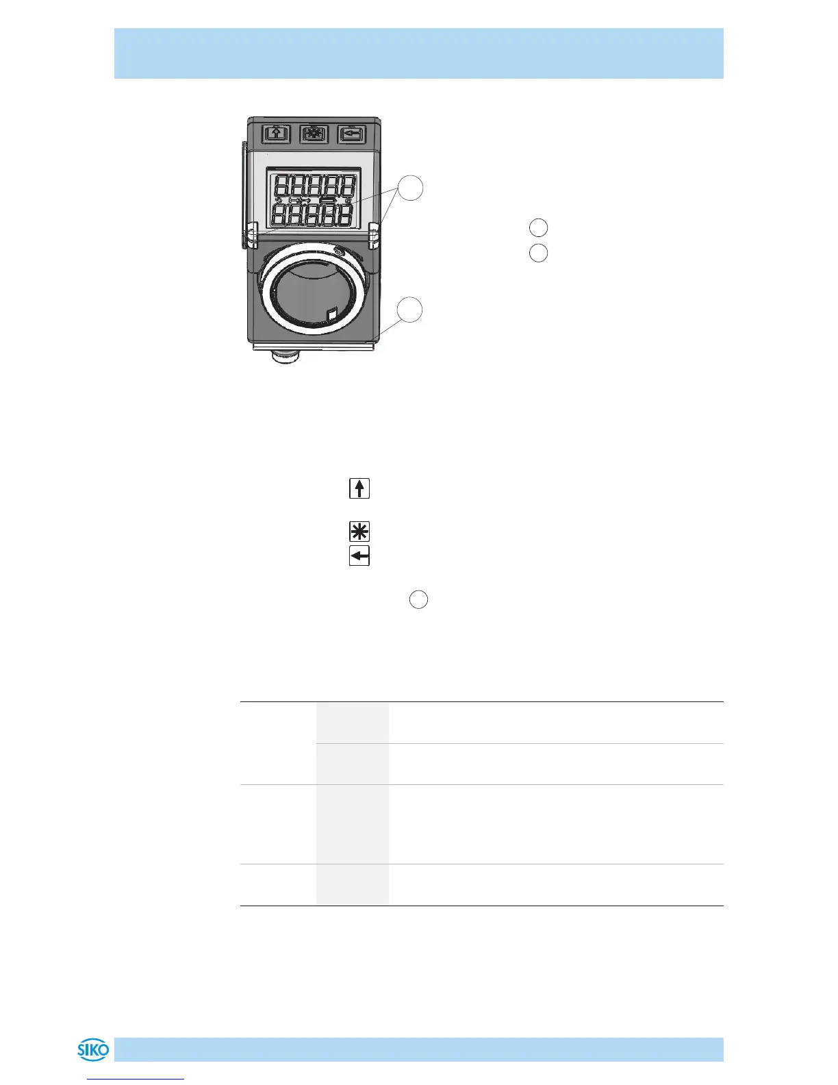
Fig. 8: Operating elements
1
Position monitoring LEDs
2
Bus-LEDs
Manual setup operation
After applying supply voltage (see chapter 4.2), the position indicator will
be on the uppermost level of the menu structure (default/delivery state).
• Pressing the key enables or disables the incremental measurement
function.
• Pressing the key starts calibration (see User manual).
• Pressing the key starts the configuration mode (see User manual).
LED Position monitoring
1
In the basic state (factory setting), the LED display has the following
meaning.
Color State Description
both LED
green
on Actual position value is within the programmed
position window.
o Actual position value is outside the programmed
position window.
one LED
red
on Actual position value is outside the programmed
position window. The red LED indicates the direc-
tion of shaft rotation required to arrive at the set-
point.
both LED
red
o Actual position value is within the programmed
position window.
 Loading...


