AP05
Commissioning English
AP05 · Date 25.09.2018 · Art. No. 88847 · Mod. status 316/18
31
LED-Bus
2
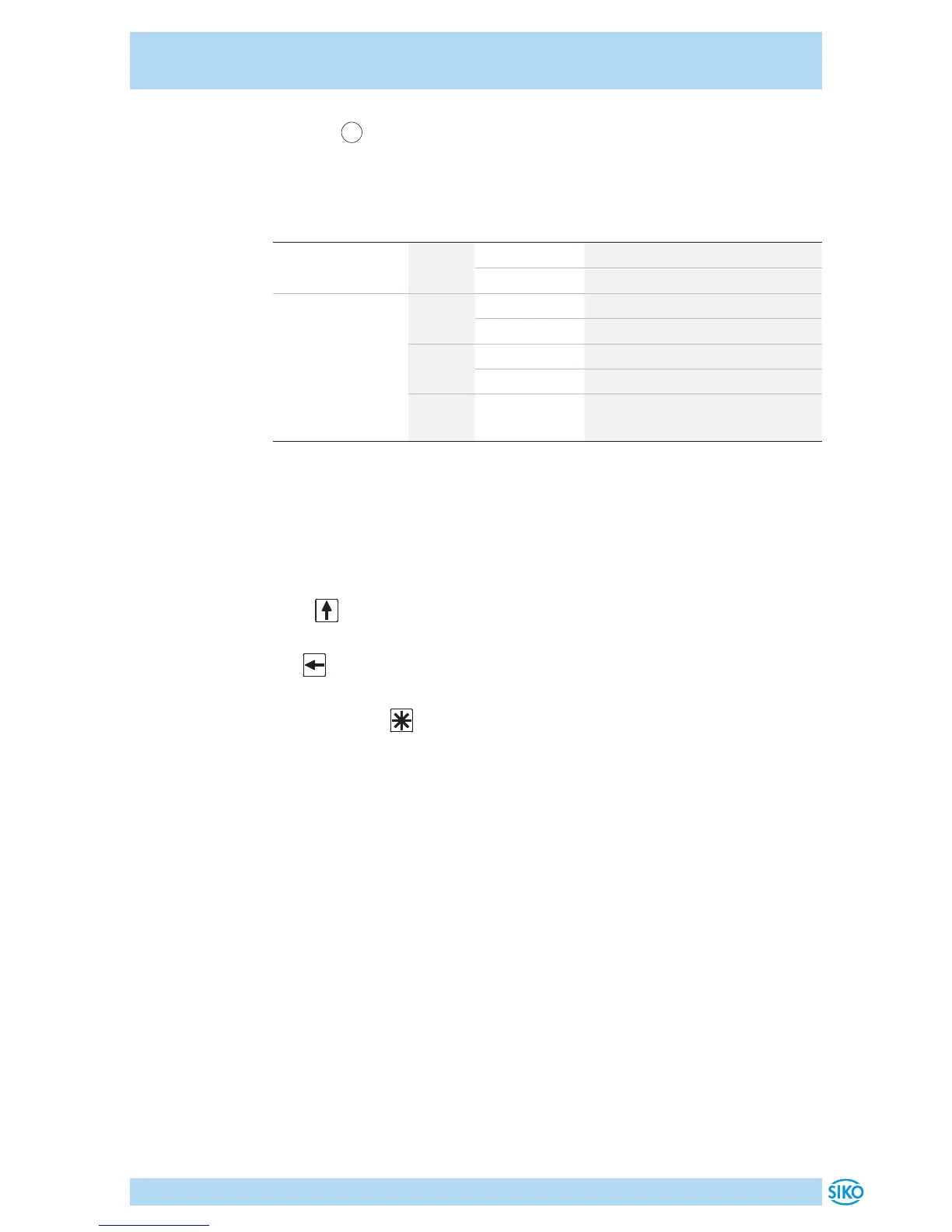
In the basic state (factory setting), the LED display has the following
meaning.
Bus connection Color State Description
RS485 yellow on bus operation active
o no bus operation
CAN green blinks NMT-state = Pre-Operational
on NMT-state = Operational
red on CAN Error = Bus o
o CAN Error = no error
red/
green
flickering
alternately
CAN-Ongoing initialization
For additional LED states and their meanings refer to the User manual.
Configuration
The required parameters are set in the configuration mode. On the 1st
line of the display, the parameter will be shown and on the 2nd line the
respective value will be displayed.
Press key for changing actual value and / or the blinking digit when
entering a multi-digit value.
The key serves for switching to the next digit in case of multi-digit
numbers.
By pressing the key, the set value is acknowledged and saved non-vol-
atilely. If no key is pressed, the configuration mode will be exited after
~30s without saving the latest value displayed, i. e. the original value will
be maintained.
For a detailed description of the configuration parameters refer to the
User manual.
Calibration
Two steps are required for executing calibration:
1. Write the calibration value in the configuration mode or via the bus
interface (see User manual)
=> Position value = current measured value + calibration value + o-
set value
2. Execute calibration (reset) (see chapter 5: Display and control keys
and Additional)
=> Position value = 0 + calibration value + oset value
Since the measuring system is an absolute system, calibration is necessary
only once with commissioning.
 Loading...


