AP05
Installation English
AP05 · Date 25.09.2018 · Art. No. 88847 · Mod. status 316/18
28
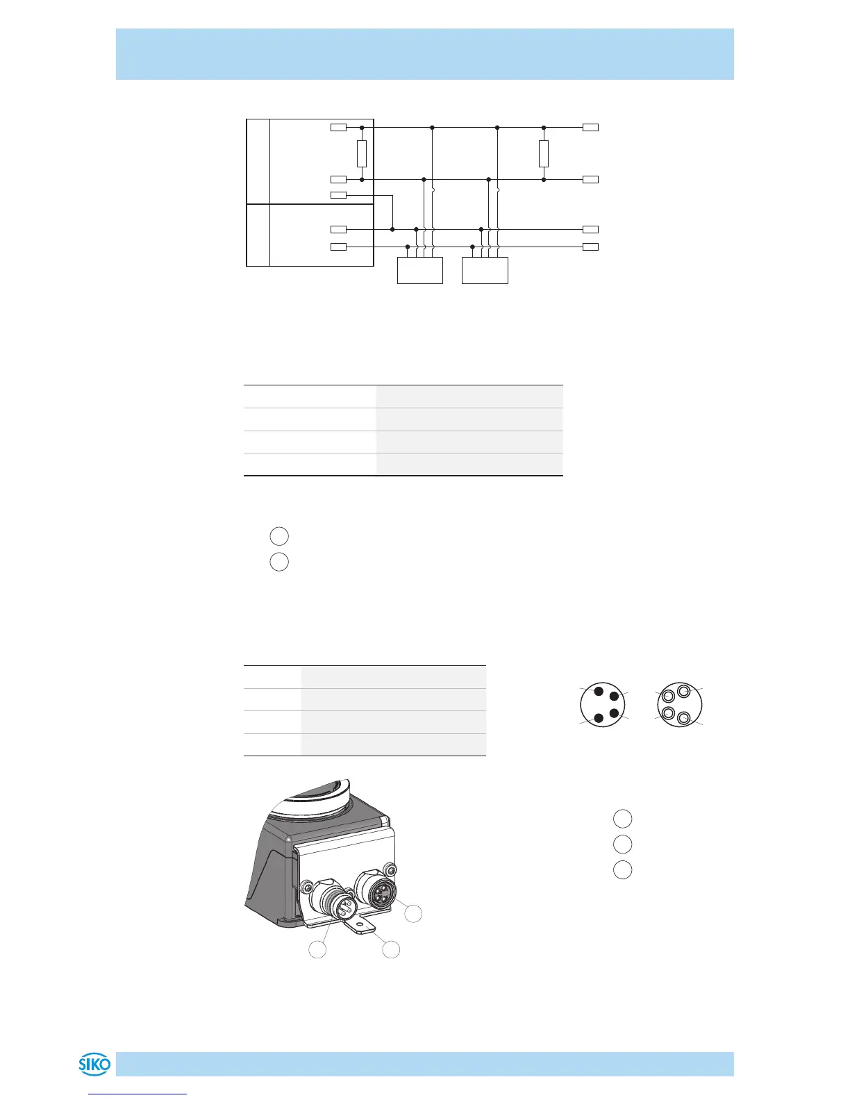
Fig. 5: Connection diagram CAN
24 V
24 V
CAN_GND
CANL
CANH
120 R
CANH
CANL
Node 1
120 R
Node n
0 V
0 V
Bus-Master
Power supply
Data transfer CAN interface
CAN baud rate max. bus network length
125kbit/s 320m
250bit/s 160m
500bit/s 80m
1Mbit/s 40m
Pin assignment
•
1
Bus IN: Pin 4 pin M8 (see Fig. 6).
•
2
Bus OUT: Female 4 pin M8 (see Fig. 6).
For cable extension, mating connector and bus terminator resistor acces-
sories see chapter 8.
PIN Designation
1 DÜB/CANL
2 DÜA/CANH
3 +UB
4 GND
1
Bus IN
2
Bus OUT
3
PE connection
2
31
Fig. 6: Pin assignment
Strand cross sections of lines 0.14 ... 0.5mm².
 Loading...


