AP05
Installation Deutsch
AP05 · Datum 25.09.2018 · Art. Nr. 88847 · Änd. Stand 316/18
7
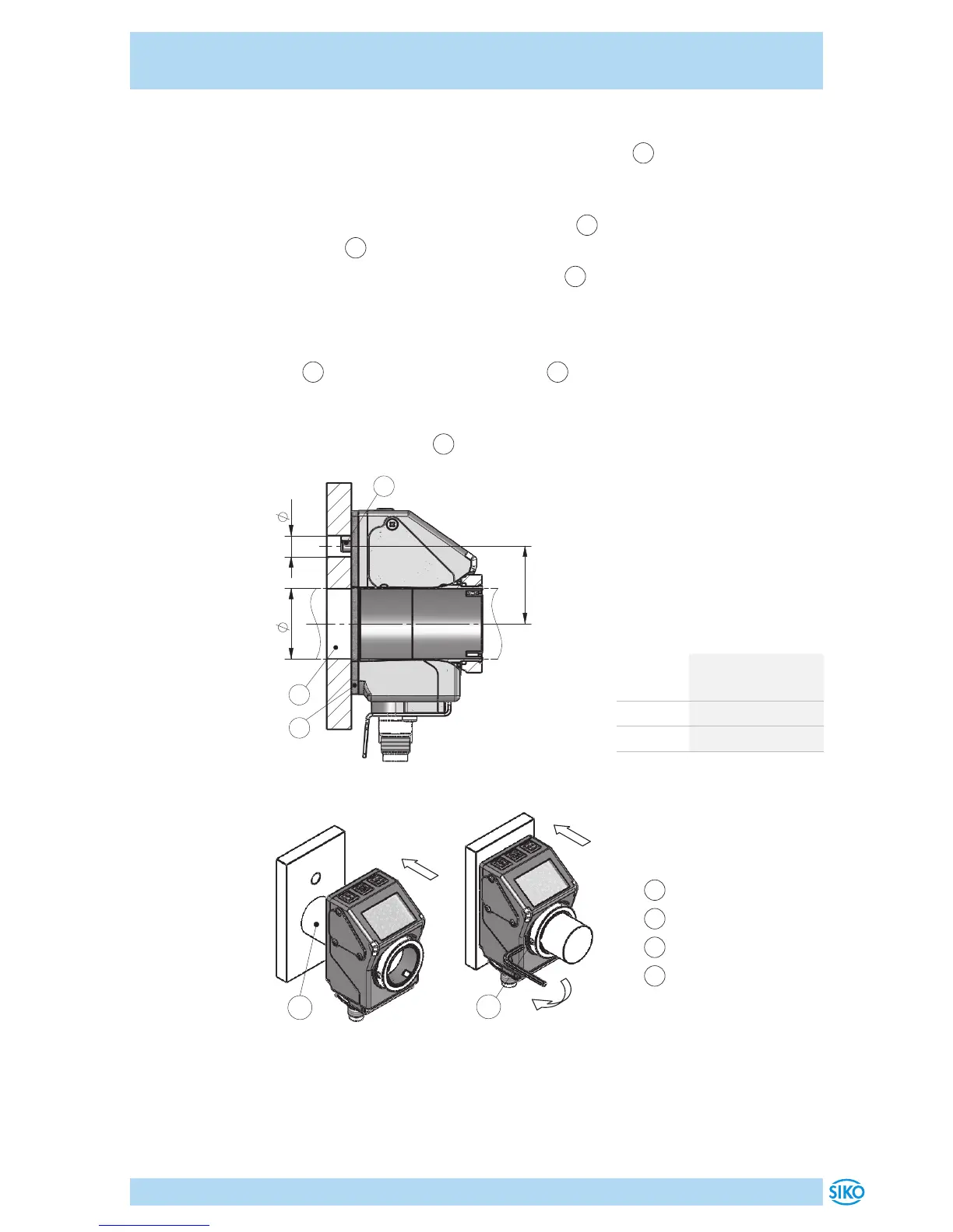
Vorbereitung Montage (Abb. 1, Abb. 2, Abb. 3):
1. Beiliegende selbstklebende Dichtungsplatte
1
(Moosgummi) auf
Lagerbügel beziehungsweise Zwischenplatte aufkleben (Sicherstel-
lung der Schutzart, ausgleichen von Unebenheiten).
2. Bohrung (ød) für Drehmomentstütze
2
auf Abstand (L1) zur Kunden-
welle
3
fertigen.
3. Durchmesser (øD) der Kundenwelle
3
beachten.
Montage (Abb. 1, Abb. 2, Abb. 3):
1. Positionsanzeige inkl. Dichtungsplatte bis Anschlag auf Kundenwelle
3
schieben. Drehmomentstütze
2
in vorhandene Bohrung einfüh-
ren (verspannungsfreie Montage). Eine Langloch für die Drehmoment-
stütze wird empfohlen.
2. Gewindestifte M3
4
mit ≤0.2Nm anziehen.
D
1
2
3
d
L1
Abb. 1: Einbaumaße
Maß ød ø6 (Form A)
ø10
+0.8
(Form B)
Maß L1 22
Maß øD ø20
(Spielpassung)
Tab. 1: Einbaumaße
1
Dichtungsplatte
2
Drehmomentstütze
3
Kundenwelle
4
Gewindestift
3
Abb. 2: Montage
4
Abb. 3: Anzugsmoment
Gewindestift
 Loading...