DE04 DE04/1 DE10
Installation English
DE04 DE04/1 DE10 · Date 10.12.2012 · Art. No. 84260 · Mod. status 384/12
19
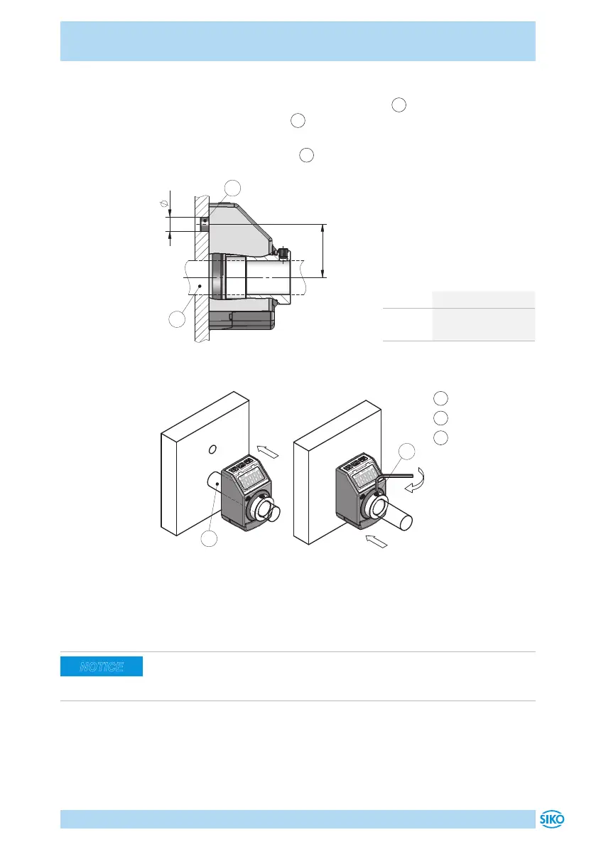
Mounting (Fig. 1, Fig. 2, Fig. 3):
1. Push the position indicator onto the shaft
2
until reaching the stop.
Insert torque support
1
into the existing bore (nondistorted mount-
ing). A long hole for the torque support is recommended.
2. Tighten grub screws M4
3
.
Fig. 1: Mounting dimensions
dim. øD ø6
dim. L1 22 (DE04, DE04/1)
30 (DE10)
Tab. 1: Mounting dimensions
Fig. 2: Mounting
Fig. 3: Fastening torque
for headless pin
1
Torque support
2
Shaft
3
Headless pin
4.2 Electrical Installation
Choose a place of operation that excludes inductive or capacitive interfer-
ence influences on the position indicator. When mounting the system keep
a maximum possible distance from lines loaded with interference.
NOTICE
 Loading...