5FAULTFINDNX2.doc Page 2 Latest update: 24 Feb -03
If the instrument shows Err 03 it means brake in the communication (time out is
10 sec.).
Test 1: Check connection and signal at the 4-pole jack plug the back of the
Instrument: Between Yellow and White you should have ~4,3 Volt AC (varying).
If ~4,3V OK do test 2. If only ~1,8 V AC, check Yellow to Screen and White to
Screen, the one with 0 V is interrupted.
Check connections, wires, lose ends, mix white-yellow etc.
If no fault on the installation is found remove Yellow and White wires connected to
term. 6 and 7 on the Server, do Test 1 on the Server output terminal 6 and 7.
If not ~4,3 Volt AC (varying) there is a fault in the Server.
If the Instrument does not start in spit of correct signal level, do test 2.
Test 2: If possible, check the same 4-pole jack plug with another working Digital
NX2/Nexus instrument to see if there is a correct Bus-signal from the plug. If this
Instrument works well there is fault in the first instrument, and it has to be replaced
and sent to Silva for further tests.
5.4 ERR 02 – BUS COMMUNICATION TEST
If the instrument show Err 02 it means that there is ”some” signal on the Bus but it is
in-correct, disturbed or of wrong type, (e.g. NMEA). Check connections, Set-up
and that white-yellow wires isn’t mixed.
5.5 NO OR WRONG VALUE ON ANALOGUE INSTRUMENT
If an Analogue instrument connected to a working NX2 bus do not show relevant
value: Check Set-up, calibration, connections, wires, lose ends and that white-
yellow wires isn’t mixed.
If customer have claim on other function, please check to confirm.
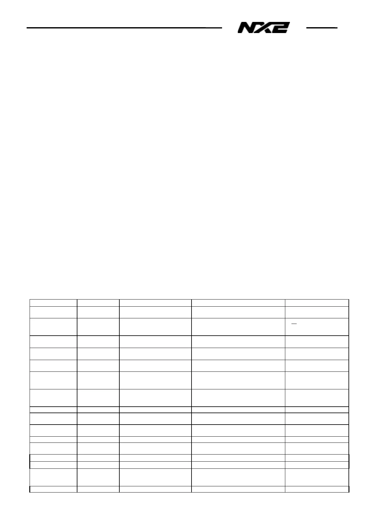
5.6 NX2 FAULTFINDING GUIDE
Multi Center can be used to find reason to system faults, see 5.8
Function Display Cause Action Set-up/ Remedy
Start Blank Display No Power Check back of Instrument Green+12V,
Screen 0 V. See §5.1
Wires, Fuse, Battery
Err 03 No Bus signal Check back of Instrument Yellow-White
4.3 V AC. See §5.3
If no signal to Instrument
check wires, connections,
Bus-signal out fr. Server
Err 03 No Bus signal Check back of Instrument Yellow-White
4.3 V AC. See §5.3
If signal to instrument, Fault
is in Instrument. Replace
Err 02 Fault or disturbance in Bus
signal
Check system and that Yellow-White
wire isn’t reversed. See § 5.4
Correct wires. Remove
spurious signal source
LCD segments
missing
LCD segments
missing
Check if all segments are present during
Start up.
Fault in Instrument
Replace
Speed/Depth/Wind/
Compass
Wrong or No
Speed/Depth/
Wind or Compass
No signal from transducer? Check signal indicators on server. see
§5.2
If No signal check wires
connections and
transducer
Speed/Depth/Wind/
Compass
Wrong or No
Speed/Depth/
Wind or Compass
Check settings per below
check list.
Correct settings! Correct settings!
Analogue
Instrument value
Wrong or No value
on Analogue Instru
Connections, wires,
calibration, Set-up
Check accordingly, see § 5.5 If fault in Instrument
Replace
Instrument Light Not all turn ON. Same ID-No on two
Instruments
Make a Re-Initialisation so that every
Instrument get its own ID-No.
BTW no values No waypoint selected Select way point
Calibration Not available/
Can’t be changed
Same ID-No on two
Instruments
Make a Re-Initialisation so that every
Instrument get its own ID-No.
Function Display Cause Action Set-up
Compass no heading [- - -] Wrong setting of COG: COG
set to ON but no navigator
connected
Set COG to OFF C94
Compass no values [- - -] Nexus com
ass transducer Set C75 to OFF C75