5
Figure 3
6.
7. Secure two stop spacers (#10) to pole, as shown in Figure
4, using one hex bolt (#22) and one lock nut (#4).
NOTCHES IN BASE
PLATE MUST BE ON
SIDE AS SHOWN
FRONT
BACK
SIDE
5. Lay Pole Assembly on its side on two padded saw horses. Slide
tab on Actuator (#16) between Post Ears (#30) and secure
using one bolt (#19), two washers (#20) and one lock nut
(#4). See Figure 4. Tighten bolts tight.
Figure 4
21
SILVERBACK ASSEMBLY INSTRUCTIONS (Day 5)
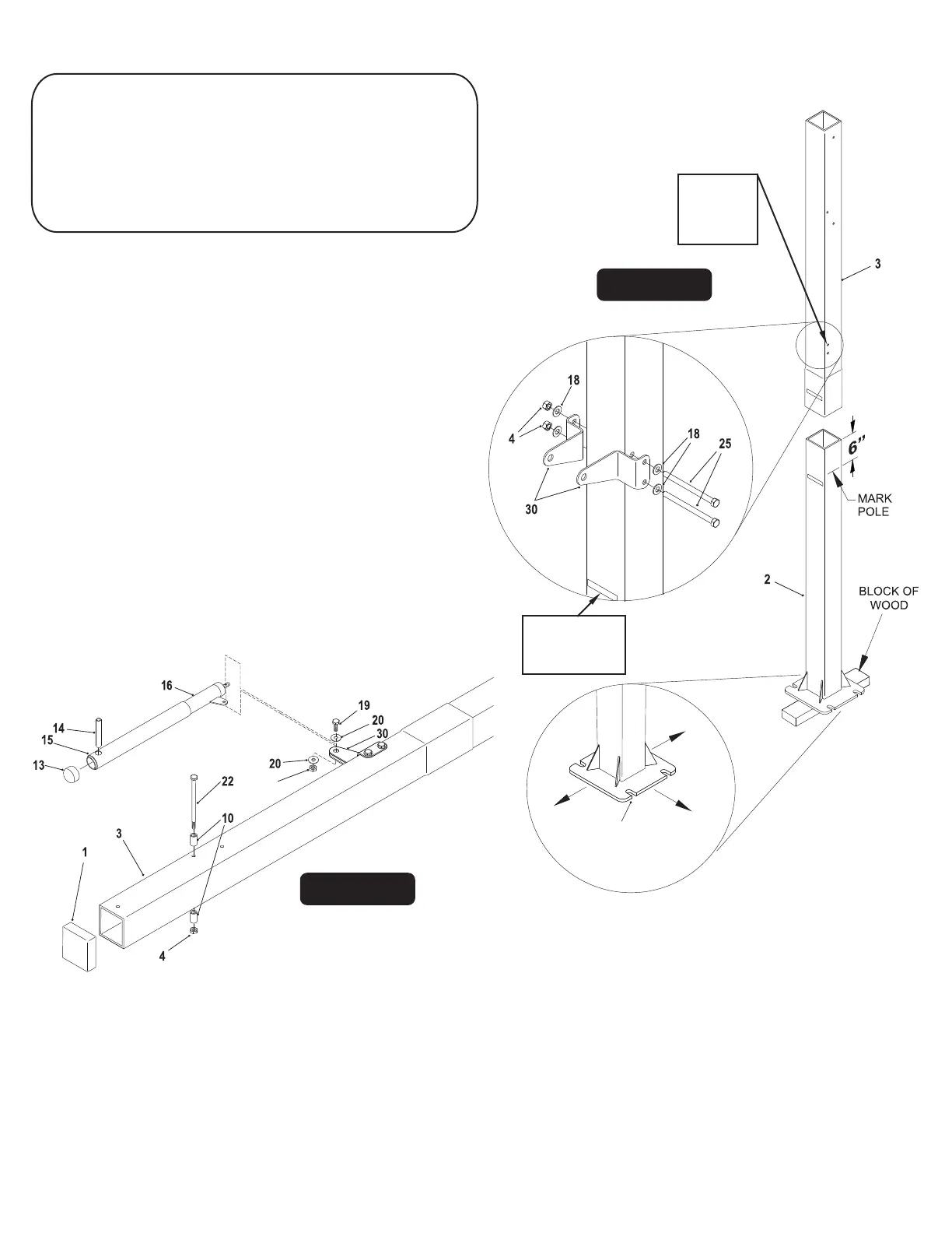
3. Attach Post Ears (#30) to holes near the bottom of Top
Post (#3) using two hex bolts (#25) four washers (#18)
and two lock nuts (#4). See Figure 3.
TOOLS REQUIRED FOR THE FOLLOWING STEPS
1 - 15/16" Open end Wrench
1 - 15/16” Socket and Ratchet (optional)
1 - 9/16” Deep Well Socket & Ratchet
1 - 3/4” Socket & Ratchet
1 - 3/4” Open end Wrench
1 - Phillips Screwdriver
1 - Level
1 - Tape Measure
1 - Rubber Mallet
1 - Set of Padded
Saw Horses
4.
Note: If necessary, use a rubber mallet to tap in
Pivot Tube (#14)
1 - 9/16” Open end Wrench
1 - Pair of Safety Glasses
Be sure that
the holes are
toward the
back of the
pole.
IMPORTANT! Nylon washers (#5) adequately space
painted parts at all pivot points. Neglecting the use of
these washers will result in rusted parts.
NOTE: All board arms are made of rectangular tubing.
Tightening hardware too tight may damage tubing
and make adjustment of system difficult.
1.
2.
Align the upper pole (#3) with the bottom pole (#2) as
shown in Figure 3 and slide them together. Stand poles up
on a block of wood, lift poles up and hit on a block of
wood until the bottom of the upper pole reaches the 6”
mark on the bottom pole. Hit poles a minimum of 7 times.
This is a friction-locking joint and requires no hardware.
IMPORTANT! DO NOT hit poles with hammer or
sledge hammer to slide poles together.
Place Pole Cap (#1) onto top of Top P
ole (#3). Note: Pole
Cap may be pre-installed by the factory.
Slide Actuator Sleeve (#15) over Actuator (#16) and place
Actuator Cap (#13) on top. Slide Pivot Tube (#14) through hole
near top of Actuator & Actuator Sleeve until equal amounts
stick out through both sides of Actuator. See Figure 4.
BAC SIDE
K
BACK SIDE
CBA
K SIDE
Match up both
“Back Side”
stickers on the
back of the poles.
Before putting any of the poles tubes together, mark bottom
pole (#2) 6 inches from the top end. Be sure to match up
both “Back Side” stickers on the back of the poles
and that the holes on top pole are toward the back.
See Figure 3.
 Loading...