8
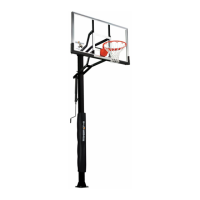
19. Remove protective backboard covering and mount Goal
Assembly (#28) and Rim Pad (#27) to Backboard, as shown
in Figure 11, using four bolts (#49), four washers (#26), and
four locknuts (#4). Tighten fasteners finger tight, leave them
loose enough to level rim.
20. Place a level across rim assembly and adjust rim until it is
level. Finish tightening the four nuts.
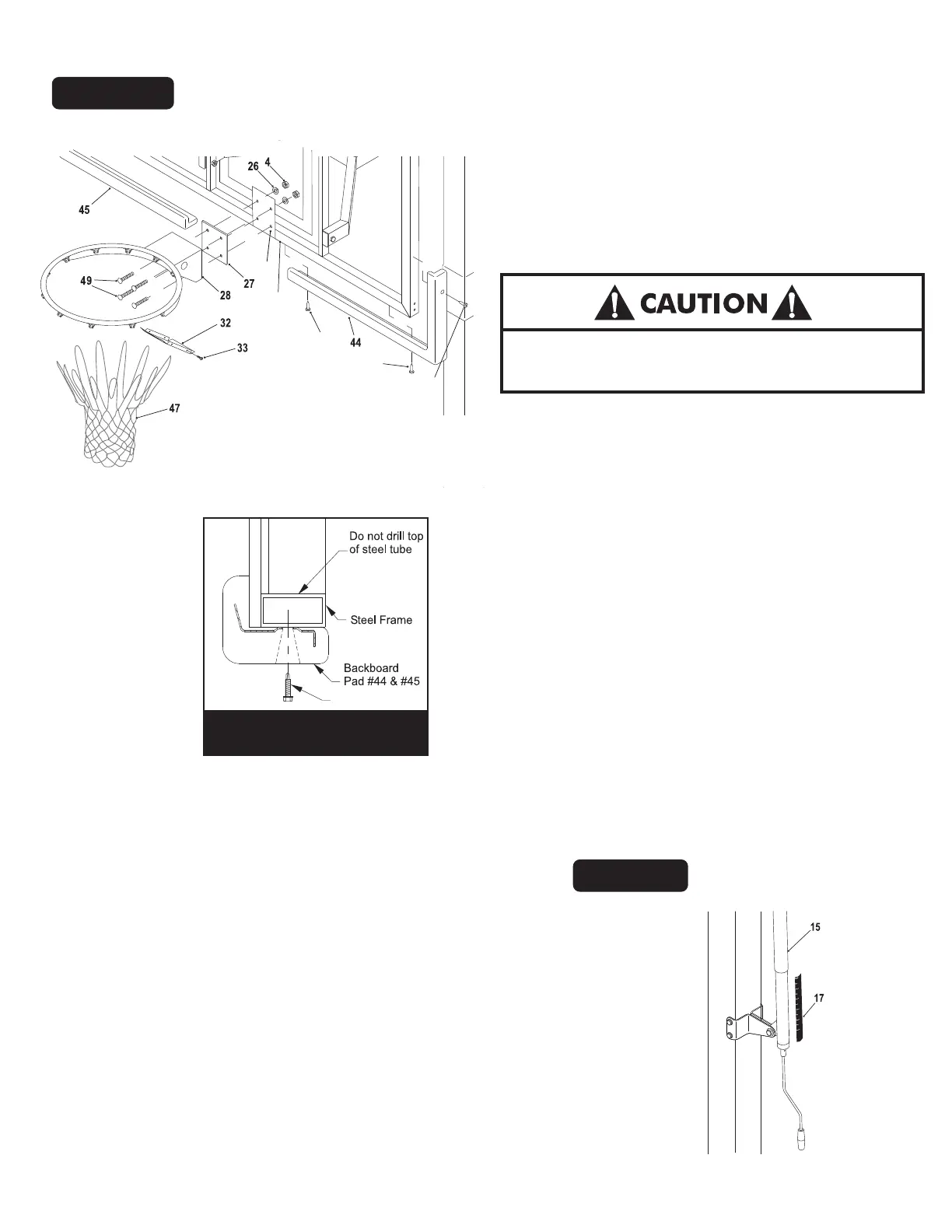
26. Adjust unit to 7-1/2 feet. Use a tape measure to measure from
the top of the rim to the playing surface. Stick Height Decal
(#17) to back of Actuator (#16) with the "7.5" mark aligned
with bottom of Actuator Sleeve (#15). See Figure 12.
Figure 12
21. Attach Rim Cover Plate (#32) using four screws (#33). See
Figure 11.
22. Check all nuts and bolts and make sure everything is
tightened properly.DO NOT over tighten pivot points,
snug is tight enough.
23. Use the Backboard Pads (#44) and (#45) as a template and
mark the hole locations on the backboard frame. See Figure
11 and Detail A.
NEVER USE RIM WITH COVERPLATE REMOVED!
Figure 11
77
77
29
23
77
Screw #77
Detail A
24. Drill 9/64" pilot holes into steel backboard frame. See
Detail A. Do not drill through both sides of tube.
25. Secure Backboard P
ads (#37) and (#38), as shown, using
screws (#42). Note: Tighten screws tight but, do not over
tighten screws.
Note: Safety glasses required for Step 24.
Do not over tighten screws.
Note: Cordless drill recommended for screw installation.
 Loading...