17
ELECTRICAL
SYSTEM
________________
This section describes the various compo-
nents of the Electrical System on your 352
MY and also includes a Trouble Shooting
Guide for your convenience.
Power Systems
Operation Procedures Batteries
The DC Electrical System obtains its source
of power from two (2) batteries, located
in the engine compartment. The negative
terminal of each battery is attached to a
grounding stud on each engine. This is
known as a “negative ground system” and is
the approved system for marine DC electri-
cal systems. The battery wiring system has
two color-coded wires. The yellow wire is the
ground (negative) wire and the red wire is
the positive (“hot”) wire. Both batteries are
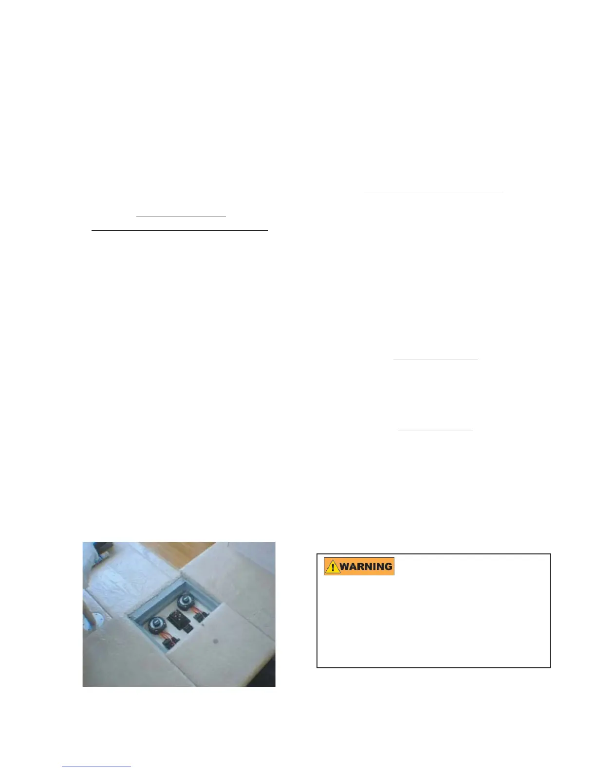
connected to a battery switch (See photo-
graph below, which illustrates the location
of the battery switches). The positions on
the battery switch are ON and OFF. The
switch must be turned to the ON position to
supply power to the DC electrical system.
When the battery switch is turned to the OFF
position, power is disconnected to the DC
electrical system.
NOTE: The bilge pumps, carbon monoxide
detector and radio memory are NOT discon-
nected from their power source when the
battery switch is turned to the OFF position.
These accessories are connected directly
to the battery and do not require a switch
for operation.
Battery Charging System
The batteries maintain their charge from
alternators, which are located on each en-
gine. The alternators supply charging power
to the batteries only while the engines are
running. Your 352 MY also has a converter,
located in the bilge, which converts 120 volt
AC electrical power from either the genera-
tor or shore power into 12 volt DC electrical
power.
DC Main Panel
Turn ON DC main breaker switch on the
main distribution panel.
Shore Power
Follow the procedures below to connect
shore power to your yacht:
Turn OFF all 120 volt circuit breakers at
the main distribution panel. Shut down
the generator if it is in operation.
Using a damaged or im-
proper cord for shore power connection
can cause electrical shock and serious
personal injury. Use a cord specifi cally
designed for shore power connection.
DO NOT use a household extension
cord.
•