Smart Machine Smart Decision
SIM7600E_SIM7600E-H-PCIE_Hardware_Design_V1.00 24 2017-11-23
Note: SDA and SCL are pulled up to 1.8V via 2.2K resistors in module. So external pull up resistors are not
needed in application circuit. For more details about I2C AT commands please refer to document [1].
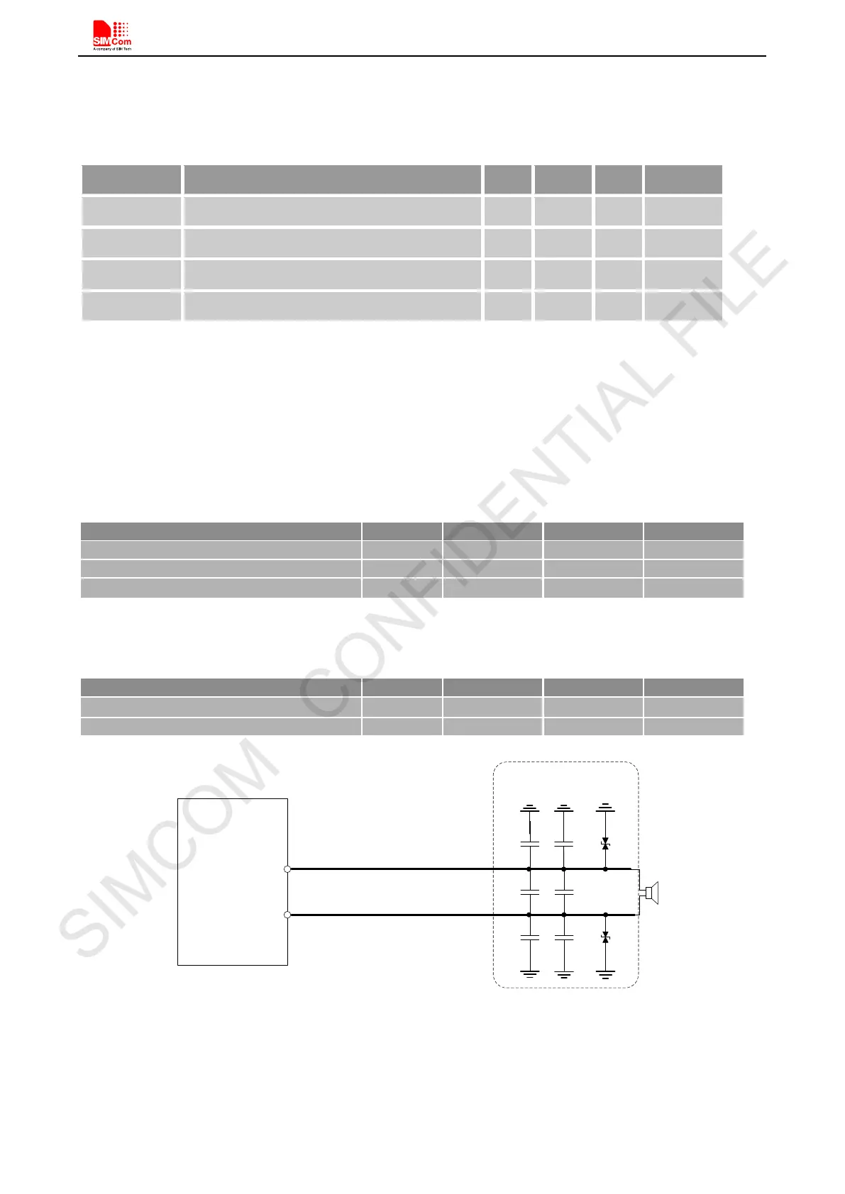
Table 12: I2C Electrical Characteristic
Symbol Parameter
Min Typ Max Unit
V
IH
High-level input voltage
1.17 1.8 2.1 V
V
IL
Low-level input voltage
-0.3 0 0.63 V
V
OH
High-level output voltage
1.35 1.8 1.8 V
V
OL
Low-level output voltage
0 0 0.45 V
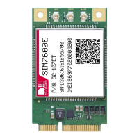
4.10 Analog Audio Interface
SIM7600E-PCIEA provides one analog signal output and one analog input. MICP/N is used as microphone input;
EARP/N is used as audio output. Regarding audio parameters configuration, please refer to the ATC manual.
Table 13: MIC input characteristics
External Microphone Load Resistance
Ω
Table 14: Audio output characteristics
Ω
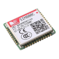
EARP
EARN
10pF
10pF
10pF
33pF
33pF
33pF
ESD
ANTI
ESD
ANTI
MODULE
The lines in bold type should be
accorded to differential signal
layout rules
These components should be
placed to speaker as close as
possible
Figure 17: Receiver interface configuration
Note: EARN is connected to GND in module, a pseudo-differential circuit is suggested.