with the eight self-tapping screws
provided;
–
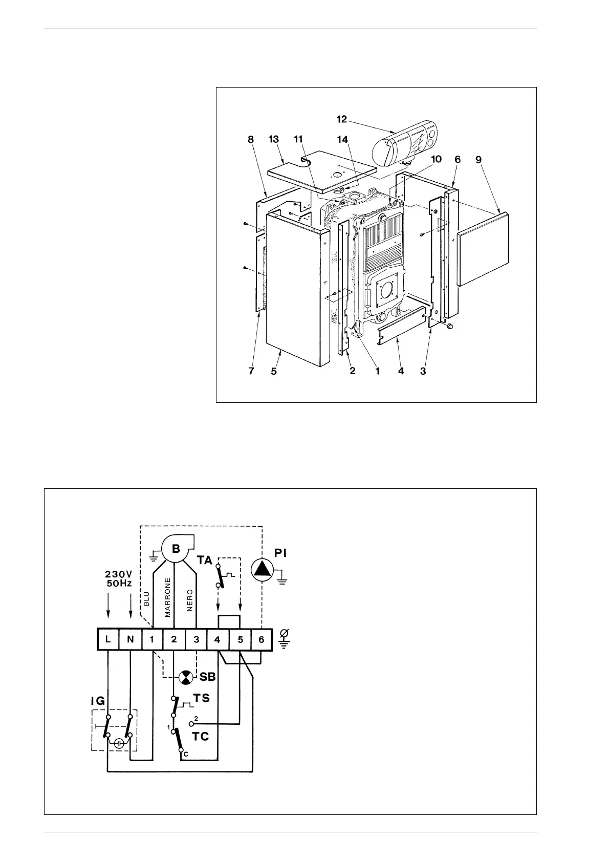
assemble the upper rear panel (8)
with the six self-tapping screws pro-
vided;
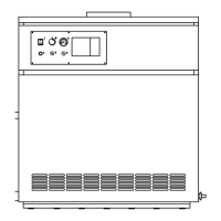
– fix the control panel (12) to the cover
(13) using the check nut (14);
– unwind the capillary tubes of the two
thermostats and thermometer by
inserting their sensors inside the
sheath (11), securing the assembly
in position using the capillary tube
retaining spring provided;
– screw the water gauge to the check
valve (10);
– complete assembly by fixing the
cover (13) and the front panel (9) to
the side parts.
NOTE: Remove the “Testing Certifi-
cate” from inside the combustion
chamber and keep together with
the instructions manual.
2.7 ELECTRICAL CONNECTION
The boiler is fitted with an electricity
cable, and requires a a single-phase
power supply of 230V - 50Hz throu-
gh the main switch protected by
fuses.
The room thermostat (required for
enhanced room temperature con-
trol) must be connected to the ter-
minals 4-5 after removing the link
(fig. 9). Connect the burner cable
supplied.
NOTE:
SIME declines all responsibility for
injury caused to persons due to fai-
lure to earth the boiler.
25
Fig. 8
KEY
IG Main switch
TA Room stat (not supplied)
PI C.H. pump (not supplied)
TC Boiler stat
TS Safety stat
B Burner (not supplied)
SB Burner lock-out lamp
NOTA: The room stat must be con-
nected to the terminals 4-5 after
removing the link.
Fig. 9