85
IT
ES
PT
GB
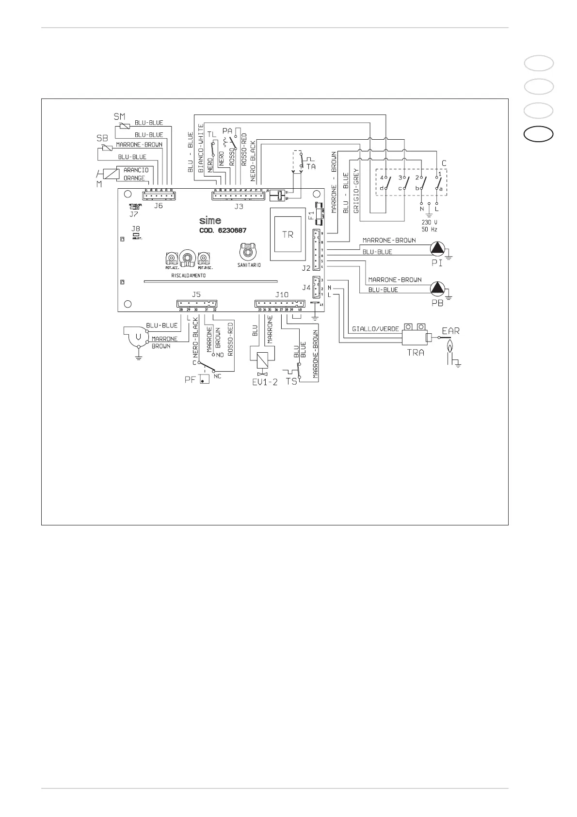
2.10.4 Wiring diagram “25/60 BF -30/60 BF”
Fig. 20/a
KEY
F1
Fuse (F 1,6A)
TR Transformer 230/24V
PI C.H. pump
PB D.H.W. pump
EV1 Gas valve coil
EV2 Gas valve coil
V Fan
PF Smoke pressure switch
TL Limit stat 80 °C
M Modulator
PA Water pressure switch
C Rotary switch
SM Heating sensor (blue)
SB D.H.W. sensor
TA Room stat
EAR Ignition/detection electrode
TRA Ignition transformer
TS Safety stat 100°C
Note: The room stat or the chro-
nothermostat must be connected
to terminals 10-11 of the “TA” con-
nector after having removed the
bridge
CONNECTOR SPARE PART CODES:
J2 cod. 6278622
J3 cod. 6278621
J5 cod. 6278625
J6 cod. 6278620
J10 cod. 6278623