4.1 D.H.W. PRODUCTION
The preparation of hot water is guaranteed
by the tank unit in glass enamelled steel
with magnesium anode for the protection of
the tank unit and inspection flange for its
control and cleaning.
The magnesium anode must be checked
annually and substituted when it is worn.
If the boiler does not produce hot water,
make sure that the air has been released
by pressing on the manual outlets after
having switched off the main switch.
4.2 ADJUSTMENT OF HEAT OUTPUT
FOR C.H. MODE
To adjust boiler heat output for heating pur-
poses, i.e., modifying the setting made at the
factory which is approximately 19 kW, use a
screwdriver to adjust the C.H. heat output
trimmer (1 fig. 22).
To increase working pressure, turn the trim-
mer clockwise; to reduce pressure, turn the
trimmer counterclockwise.
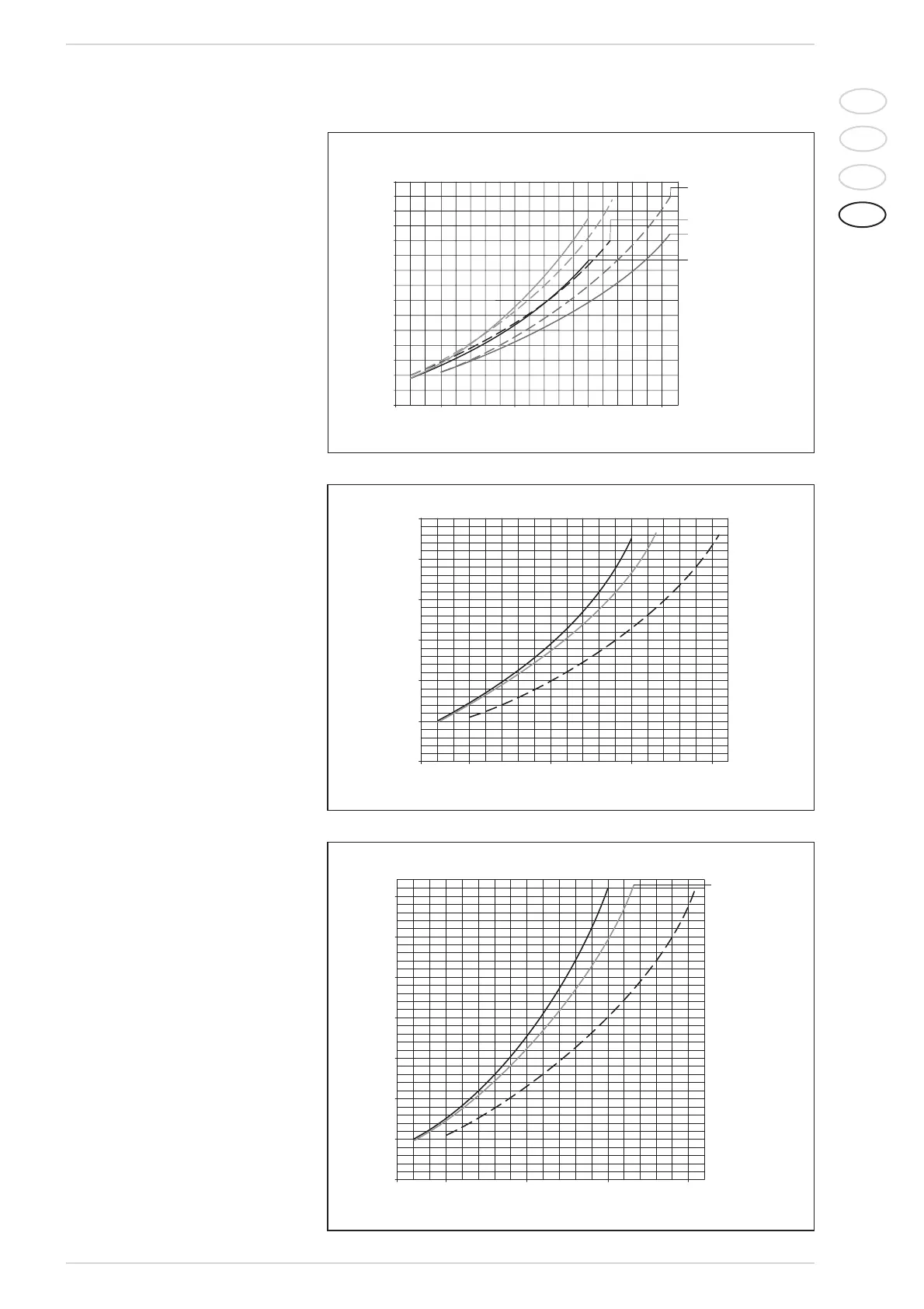
To facilitate the operations of adjusting heat
output, see the pressure/heat output dia-
grams for natural gas (methane) and buta-
ne or propane gas (figg. 26/a - 26/b -
26/c).
4.2.1 Measuring gas pressure at nozzles
To measure pressure at the nozzle, con-
nect a manometer to the intake down-
stream of the gas valve.
In “BF” models, connect the manometer as
shown in figure 27. This connection must
also be used when checking maximum and
minimum gas pressure; refer to the direc-
tions provided under point 4.4.1 if you need
to correct the settings.
4.3 GAS VALVE
The boilers are equipped standard with the
SIT 845 SIMGA/HONEYWELL VK 4105M
gas valve (fig. 28).
The gas valve is set at two pressure values:
maximum and minimum.
According to the type of gas burnt, these
correspond to the values given in Table 4.
The gas pressures at the maximum and
minimum values, are factory set. Conse-
quently they must not be altered.
Only when you switch the appliance from
one type of gas supply (methane) to
another (butane or propane), it is permit-
ted to alter the operating pressure.
4.4 GAS CONVERSION
This operation must be performed by
authorised personnel using original Sime
components.
To convert from natural gas to LPG or vice
versa, perform the following operations (fig.
89
IT
ES
PT
GB
4 USE AND MAINTENANCE