32):
– Close the gas cock.
– Disassemble the burner manifold (1).
– Replace the main nozzles (5) supplied in
a kit, inserting the copper washer (4).
Use a ø 7 spanner to perform this ope-
ration.
–
Remove the “METANO/GPL” connector
link on the card and set it in the posi-
tion corresponding to the gas to be
used (4 fig. 22).
– To set the values of maximum and mini-
mum gas pressure, follow the instruc-
tions given in section 4.4.1.
– After have ultimated the conversion of
the boiler, please stick onto the casing
panel the plate showing the relevant fee-
ding gas which is included into the kit.
NOTE: When reassembling components
which you have removed, replace gas
seals; test all gas connections after
assembly using soapy water or a product
made specifically for the purpose, being
sure not to use open flame.
4.4.1
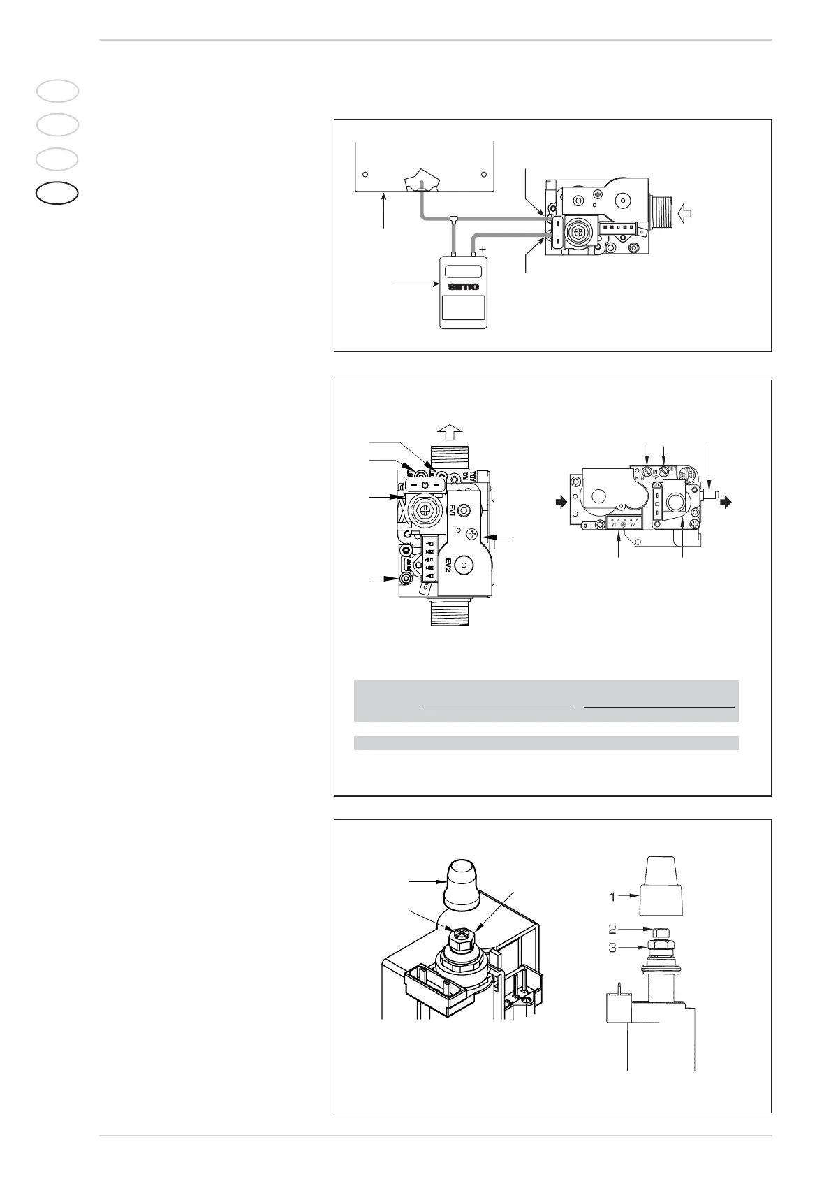
Adjusting valve pressure
Set maximum and minimum pressure on
SIT 845 SIGMA or HONEYWELL VK
4105M valves as follows (fig. 29):
– Connect the column or a manometer to
the intake downstream of the gas valve.
In “BF” models, disconnect the valve
VENT pressure test point tube (5 fig. 28).
– Remove the cap (1) from the modulator.
– Place the hot tap water potentiometer
knob at the maximum position.
– Turn on the boiler using the four-way
switch and turn on a hot water tap all
the way.
– Remember that rotating clockwise will
increase pressure while rotating anti-
clockwise will diminish it.
– Adjust maximum pressure using the nut
(3) with a wrench (10 for 845 SIGMA, 9
for VK4105) to the maximum pressure
value indicated in Table 4.
– Do not adjust minimum pressure until
you have adjusted maximum pressure.
– Turn off the supply power to the modula-
tor, and keep the hot water tap turned
on.
– Lock the nut (3) in place, turn the screw
(2) for 845 SIGMA or the nut (2) using a
7 wrench for VK4105 to the minimum
pressure indicated in Table 4.
– Turn off the boiler and turn it back on
again several times, keeping the hot
water tap turned on at all times and
checking that the maximum and mini-
mum pressure values correspond to the
established values; correct the settings if
necessary.
– Adjust, checking that you have restored
the power to the modulator.
– Put the pipe back on the valve VENT
pressure test point.
– Remove the manometer, remembering
to tighten the screw for closing the pres-
90
IT
ES
PT
GB
Fig. 29
KEY
1 Plastic tap
2 Minimum pressure adjusting nut
3 Maximum pressure adjusting nut
SIT 845 SIGMA HONEYWELL VK 4105M
TABELLA 4
Burner max. Modulator Burner min. Modulator
Type of gas pressure mbar current pressure mbar current
25/60 OF 25/60 BF 30/60 BF mA 25/60 OF 25/60 BF 30/60 BF mA
Methane (G20) 9,7 11,0 11,3 130 1,8 2,0 2,2 0
Butane (G30) 27,5 28,2 28,0 165 5,0 4,9 5,5 0
Propane (G31) 35,5 36,2 36,0 165 5,0 4,9 5,5 0
Fig. 28