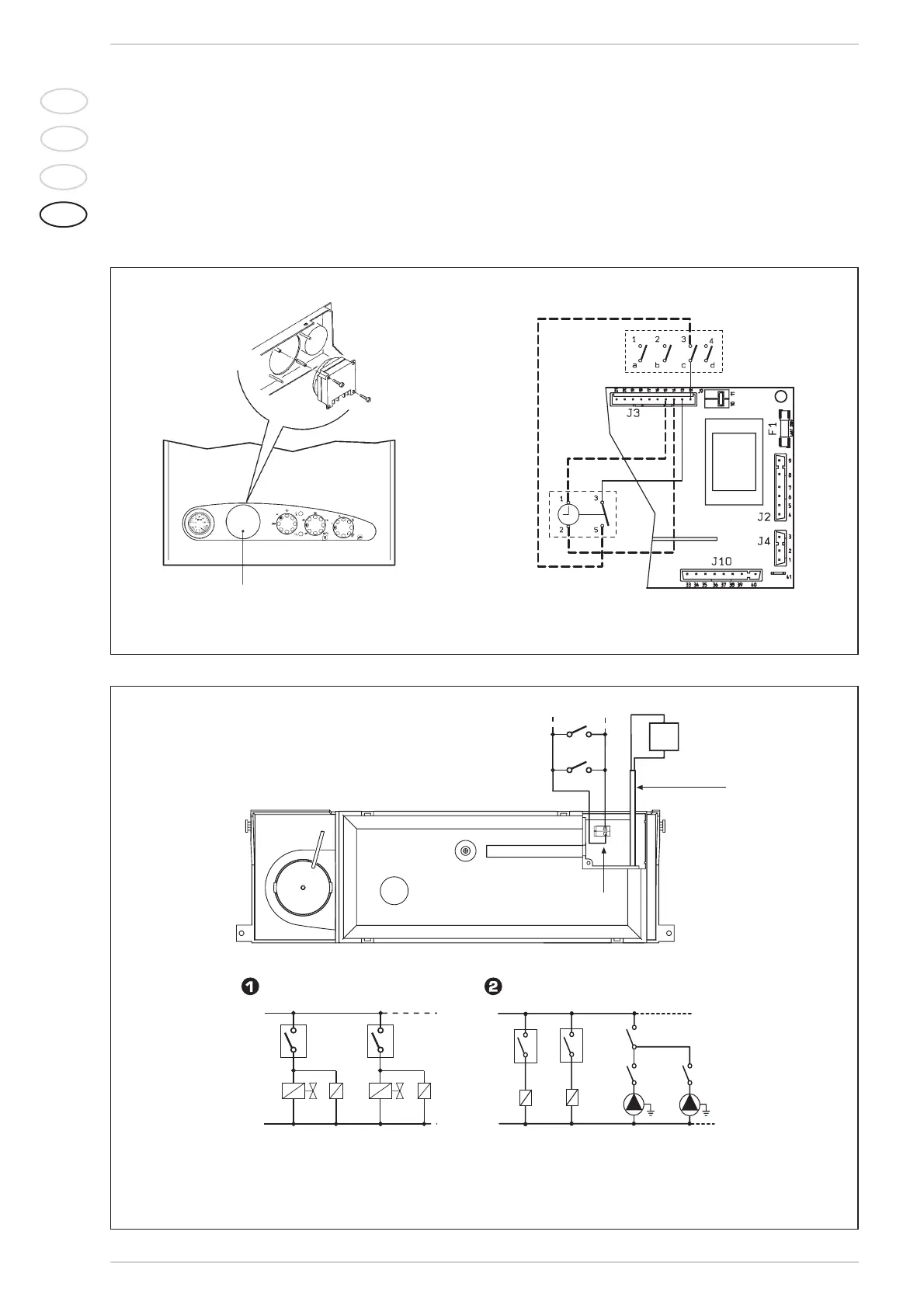
the positioning and, with the panel open, fix
the clock to the panel with the screws spe-
cifically supplied.
Remove the faston that connects terminal
3 of the rotary switch and insert it in termi-
nal 3 of the clock.
Complete the connection of the electric
clock as indicated in the diagram.
3.9 ELECTRICAL
CONNECTION
ZONE SYSTEMS
Use a separate electric line to link up the
room stats and relative zone valves or
pumps.
The connection of the micros or the
relay contacts is carried out on termi-
nals 10-11 of the “TA” connector of elec-
tronic panel after having removed the
existing bridge (fig. 25).
88
IT
ES
PT
GB
KEY
OP Time programmer
C Rotary switch
Fig. 24
REMOVE
L
N
TA
TA
1
VZ
R
VZ1
R1
CIRCUITO CON VALVOLE DI ZONA
NOTA: I relé vengono impiegati solo nel caso
le valvole di zona siano prive di micro.
CIRCUITO CON POMPE DI ZONA
CR1
CR
Connettore "TA"
10 11
RL
Cavo
pompa
impianto
NOTA: Sostituire la pompa impianto della
caldaia con il tronchetto optional cod. 8094001.
Collegare il cavo della pompa impianto ad un
relè di potenza (RL).
L
N
TA1
CRL
R1
P
TA
R
P1
CR
CR1
LEYENDA
TA-TA1 Zone room stat
VZ-VZ1 Zone valve
R-R1 Zone relay
CR-CR1 Relay contact or micro zone valve
P-P1 Zone pump
RL Power relay
CRL Power relay contact
Pump cable
“TA” connector
CIRCUIT WITH ZONE VALVES CIRCUIT WITH ZONE PUMPS
NOTE: Relays are used only if the area
valves have no microswitches.
NOTE: Replace the heating pump with the option-
al stub pipe, code 8094001. Connect the pump
cable to a power relay (RL).
Fig. 25