8
APPLIANCE PACKAGE:
- boiler (assembled);
- installation and servicing instructions;
- users instructions;
- wall mounting bracket;
- fixing screws with wall plugs.
3.1 FIXING THE WALL MOUNTING BRACKET
Before installing the appliance ensure that the chosen loca-
tion is suitable (section 2.2) and that the requirements for
flue position, (section 2.3), and minimum clearances, (
Table 2
)
are satisfied.
These minimum clearances are essential to provide access
for servicing, and are included on the wall mounting tem-
plates.
– Open the paper wall mounting templates. If a rear flue is
to be used, discard the side templates and secure the
rear template in the desired position. For a side flue appli-
cation, secure both the rear and appropriate side tem-
plate in position.
– Mark the position of the two wall mounting bracket fixing
holes and the flue/air duct hole on the appropriate wall(s).
– Remove the template(s) and drill the two fixing holes using
a 10 mm masonry drill. Fit the plastic plugs provided.
– Cut the hole in the wall for the flue/air duct. The diame-
ter should not be less than 100 mm (4 in) and must be
horizontal. Refer to fig. 12-14.
– Accurately measure the wall thickness, and note this
dimension for later use.
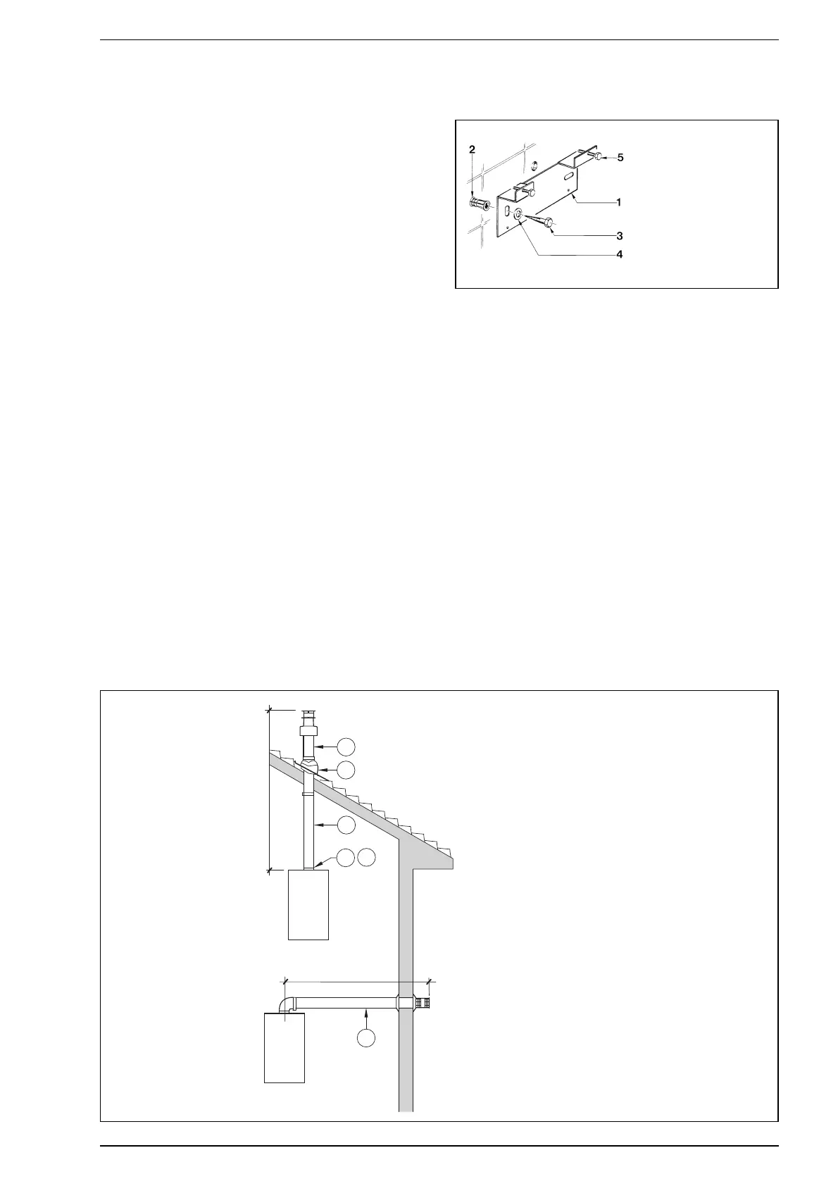
– Secure the wall mounting bracket in position using the
screws provided. Ensure that it is the correct way up, as
indicated in fig. 6.
3.2 HANGING THE BOILER
– Lift the appliance into position. The upper cross member
locates onto the wall mounting bracket.
– Screw in the wall mounting bracket adjusting screws until
the appliance is secure and vertical.
3.3 FLUE DUCTS MODEL “34I BF”
The air inlet-smoke outlet assembly ø 60/100 is supplied in a
kit code 8084811 complete with mounting instructions.
With the curve supplied in the kit the maximum horizontal
length of the flue must not exceed 3 metres.
When the extension code 8086908 is used, the end of
the flue must always have a horizontal outlet.
The diagrams in fig. 7 illustrate a number of examples of dif-
ferent coaxial outlets.
3 INSTALLING THE BOILER
Fig. 6
KEY
1 Wall mounting bracket
2 Plastic wall plug (2 Off)
3 Woodscrew (2 Off)
4 Washer (2 Off)
5 Adjustment screw (2 Off)
KEY
1 Coaxial flue kit code 8084811
2 a Extension L. 1000 code 8096100
2 b Extension L. 500 code 8096101
3 Vertical extension L. 200 code 8086908
4 Additional 90° curve code 8095800
6 Articulated tile code 8091300
7 Roof outlet terminal L. 1284 code 8091200
8 Vertical condensation collector L. 200 code 8092803
Fig. 7
IMPORTANT:
– Each additional 90° curve installed reduces
the available length by 0.90 metres.
– Each additional 45° curve installed reduces
the available length by 0.45 metres.
– It is advisable to assemble the condensation
collector (8) on vertical segments exceeding
2.5 metres in length and to limit maximum
length to 4 metres.
max 3 m
min. 1,3 m - max. 3 m