It is important that the boiler is initially
filled and started for the first time using
the method shown in 2.3.3 section e).
This procedure should also be used when
refilling after draining a boiler.
The boiler must be installed in a fixed loca-
tion and only by specialized and qualified per-
son in compliance with all instructions con-
tained in this manual. The installation of this
boiler must be in accordance with the rele-
vant requirements of the current Gas
Safety (installation and use), the local build-
ing regulations, and and I.E.E. wiring regula-
tions. Detailled recommendations for air
supply are given in BS5440:2. The following
notes are for general guidance: it is not nec-
essary to have a purpose provided air vent
in the room or compartment in which the
appliance is installed.
2.1 ANTI-FREEZE FUNCTION
The boilers are equipped with anti-freeze
function which activates the pump and the
burner when the temperature of the water
contained inside the appliance drops to
below value PAR 10. The anti-freeze func-
tion can only operate if:
– the boiler is correctly connected to the
gas and electricity supply circuits;
– the boiler is switched on;
– the boiler ignition is not locked out;
– the essential components of the boiler
are all in working order
In these conditions the boiler is protected
against frost down to an environmental
temperature of -5°C.
ATTENTION:
In the case of installation in a place where
the temperature drops below 0°C, the
connection pipes must be protected.
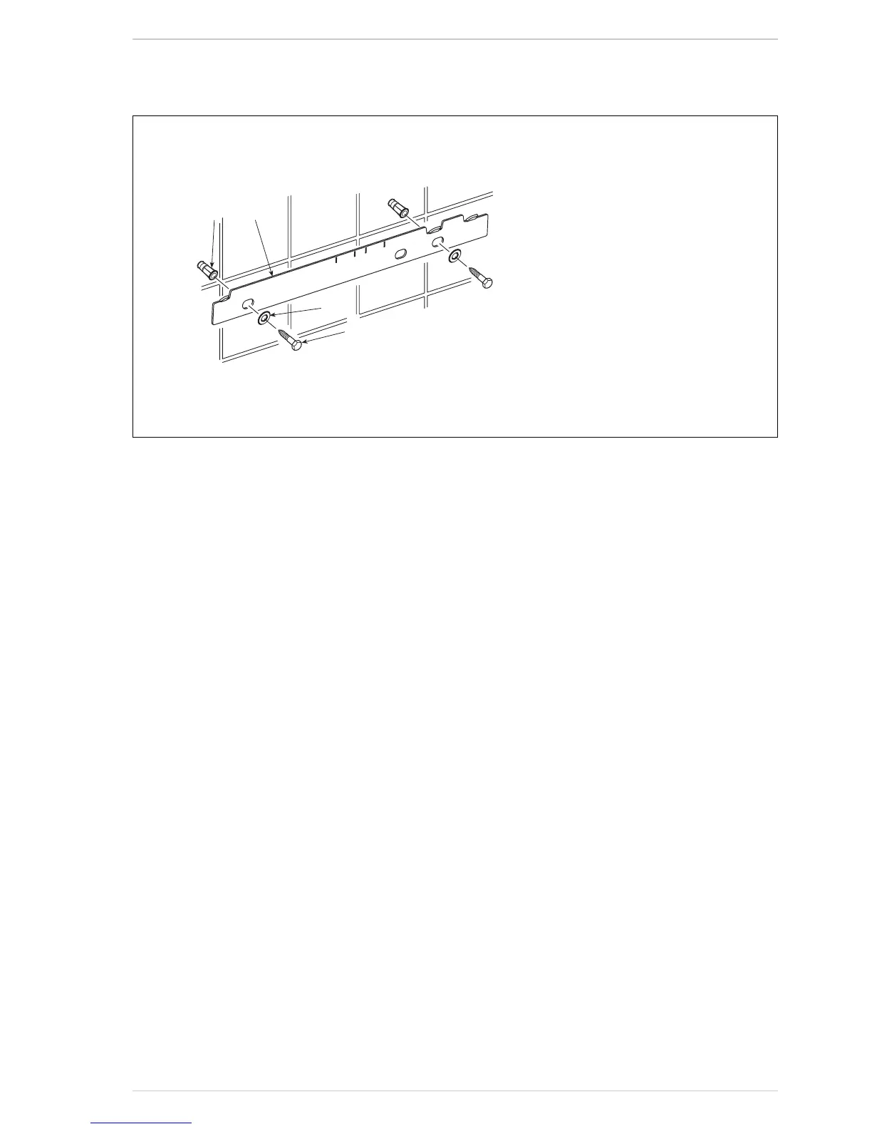
2.2 FIXING THE WALL
MOUNTING BRACKET (fig. 4)
– Mark the position of the two wall mount-
ing bracket fixing holes and the flue/air
duct hole on the appropriate wall(s).
–
Drill a top two fixing holes using a 10 mm
masonry drill and fit the plastic plugs provided.
– Accurately measure the wall thickness,
and note this dimension for later use.
– Secure the wall mounting bracket in
position using the screws provided.
Ensure that it is the correct way up, as
indicated in fig. 4.
2.3 CONNECTING
UP SYSTEM
Before connecting the boiler it is recom-
mended that the system be flushed in
accordance to BS 7593, to eliminate any
foreign bodies that may be detrimental to
the operating efficiency of the appliance.
When connecting up the boiler the clear-
ances in fig 1 should be respected.
The boiler is supplied with a valve pack part
number 5184817A. The boiler can be filled
and pressure tested prior to any electrical
supply being connected with the use of the
analogue pressure gauge. see fig 22/a
A safety valve set at 3 bar is fitted to the
appliance, the discharge pipe provided
should be extended to terminate safely
away from the appliance and where a dis-
charge would not cause damage to per-
sons or property but would be detected.
The pipe should be a minimum of 15 mm Ø
and should be able to withstand boiling
water, any should avoid sharp corners or
upward pipe runs where water may be
retained.
Gas Connection
The gas connection must be made using
seamless steel or copper pipe.
Where the piping has to pass through walls,
a suitable insulating sleeve must be provid-
ed. When sizing gas piping, from the meter
to the boiler, take into account both the vol-
ume flow rates (consumption) in m
3
/h and
the relative density of the gas in question.
The sections of the piping making up the sys-
tem must be such as to guarantee a supply
of gas sufficient to cover the maximum
demand, limiting pressure loss between the
gas meter and any apparatus being used to
not greater than 1.0 mbar for family II gases
(natural gas).
An adhesive data badge is sited inside the
front panel; it contains all the technical data
identifying the boiler and the type of gas for
which the boiler is arranged.
2.3.1 Connection of condensation
water trap
To ensure safe disposal of the condensate
produced by the flue gases, reference
should be made to BS6798:2009.
The boiler incorporates a condensate trap
which has a seal of 75mm, therefore no
additional trap is required. The advised
method of connection to the condensate
trap is by using 20mm overflow pipe with a
socket attached to cover the condensate
trap connection.
The condensate should ideally be dis-
charged internally into an internal waste
pipe(washing machine/sink waste) or a soil
pipe to avoid the risk of freezing.
External pipe runs should be avoided, but
if it is necessary, the pipework should be
at least 32mm and protected from the
risc of freezing with a waterproof insula-
tion and the length kept to a minimum
and not exceeding 3 m. termination
should be into an external gully or pur-
pose made soakaway.
2 INSTALLATION
10

 Loading...