16
Voltage free option
A voltage free control, room thermostat or pro-
grammable room thermostat, can be connec-
ted after removal of the wire link, to the TA con-
nections on the voltage free input connector.
If required a combination of voltage free room
thermostat and a separate voltage free time
clock can be connected. The room thermostat
to the TA connection, and the time clock to the
OP connection, after removing the links.
240 volt option
The heating demand can be controlled by a 240
volt switched demand-such as a room thermo-
stat, time clock or the demand from a Y or S
plan.
Connect the switched demand to terminal 1 on
the 240 volt expansion board, and remove the
link in the TA connection on the voltage free
inputs (if the TA link is not removed the boiler will
work in the heating mode without a demand).
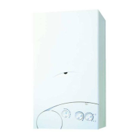
2.9.2 Connection of RF Clock
kit Sime part number 7102604
(BCG part 138493) (fig. 10/a)
Ensure that the boiler is isolated from the power
supply. To enable ease of fitting a 1 meter cable
is supplied within the boiler.
Mount the receiver close to the boiler at least
1.5 metres above the floor. Avoid any location
that would cause receptions problems. Connect
the boiler to the receiver as shown. Remove the
wire link in the TA connection at the boiler and
do not forget to link the “L” and “1” terminals at
the RF Receiver (fig. 10/a).
2.9.3 Climatic control option
The boiler is designed for connection to an
external temperature sensor, supplied on reque-
st (code 8094101) in conjunction with remote
control (code 8092226), which can automati-
cally regulate the temperature value of the boi-
ler output according to the external temperatu-
re.
For installation, follow the instruction in the
package. Expansion control kit 8092240 will
also be required.
2.9.4 Use with different
electronic systems
Some examples are given below of boiler
systems combined with different electronic
systems.
Where necessary, the parameters to be set in
the boiler are given.
The electrical connections to the boiler refer to
the wording on the diagrams (fig. 11 - fig. 11/a).
Zone valve control is activated with every hea-
ting request from remote control.
Description of the letters indicating the compo-
nents shown on the system diagrams 1 to 6:
M C.H. flow
R C.H. return
CR Remote control CR 63
SE External temperature
sensor
TA 1-2 Zone room thermostat
VZ 1-2 Zone valve
RL 1-2 Zone relay
Sl Hydraulic separator
P 1-2 Zone pump
IP Floor system
EXP Expansion card
(code 8092240)
VM Three-way mixer valve
TSB Safety thermostat
low temperature
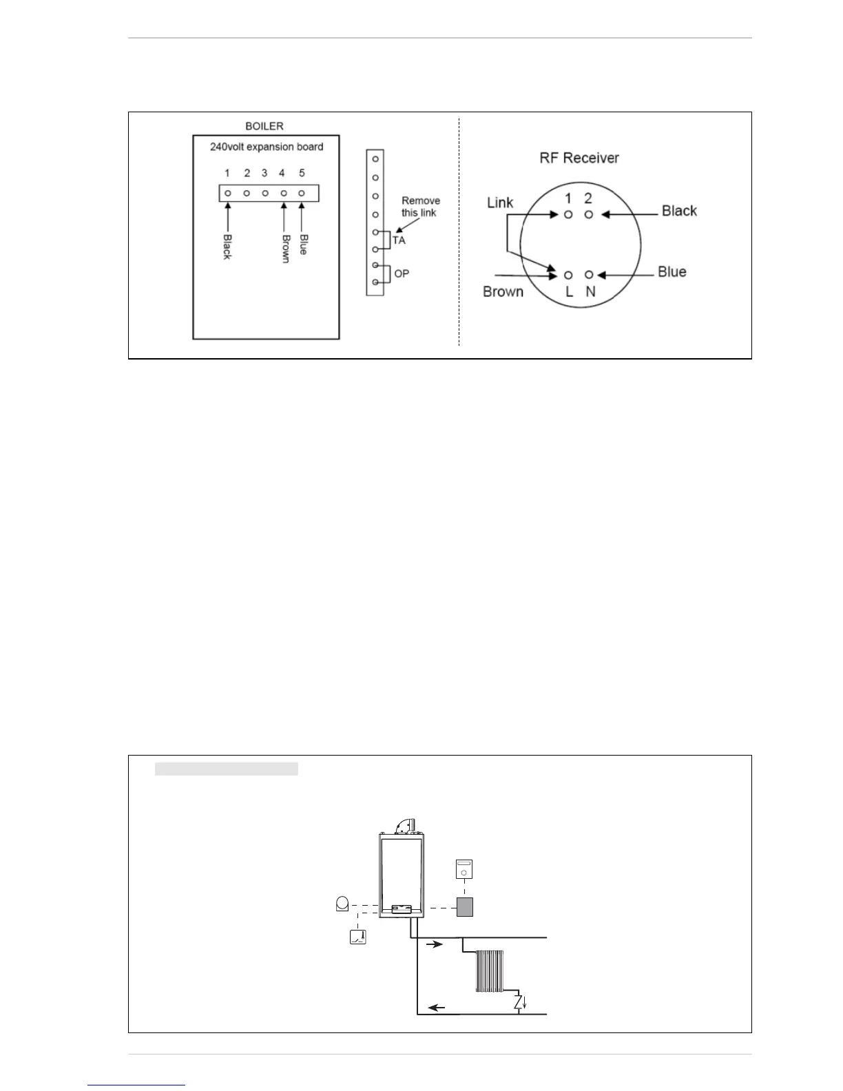
1 BASIC SYSTEM
SYSTEM WITH A DIRECT ZONE AND ROOM THERMOSTAT, OR WITH A REMOTE CONTROL (Code 8092219), KIT
EXPANSION REMOTE CONTROL (Code 8092240) AND EXTERNAL SENSOR (Code 8094101)

 Loading...