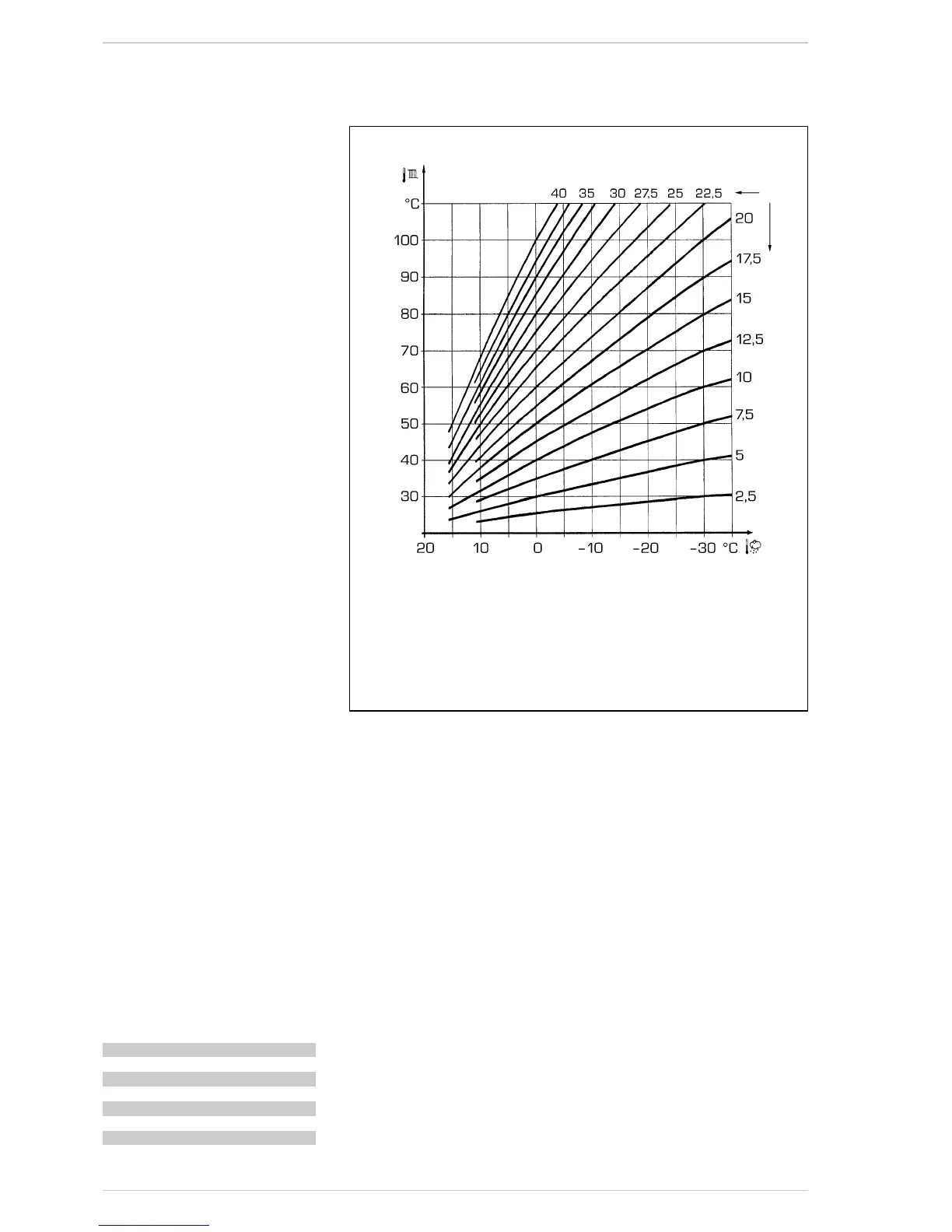
3.3 EXTERNAL SENSOR (fig. 13)
If there is an external sensor, the heating
settings SET can be taken from the climatic
curves according to the external tempera-
ture and, in any case, limited to with the
range values described in point 3.2 (para-
meters PAR 13 and PAR 14).
The climatic curve to be set can be selected
from a value of 3 and 40 (at step 1).
Increasing the steepness of the curves of
fig. 14 will increase the output temperature
as the external temperature decreases.
3.5 CARD FUNCTIONING
The electronic card has the following
functions:
– Antifreeze protection of the heating cir-
cuits.
– Ignition and flame detection system.
– Control panel setting for the power and
the gas for boiler functioning.
– Anti-jammed for the pump which is fed
for a few seconds (10”) after 48 hours of
inactivity.
– Chimney sweep function which can be
activated from the control panel.
– Temperature which can be shifted with
the external sensor connected.
– Automatic regulation of the ignition
power and maximum heating.
Adjustments are managed automatically
by the electronic card to guarantee maxi-
mum flexibility in use of the system.
– Interface with the following electronic
systems: remote control CR 73 combi-
ned with expansion card kit code
8092240.
3.6 TEMPERATURE
DETECTION
SENSOR
Table 4 shows the resistance values of the
heating, D.H.W. and fumes sensor.
If the heating sensor (SM) and fumes sen-
sor (SF) is faulty or open circuit, the boi-
ler will not function on either heating or
D.H.W.
If the D.H.W. sensor (SB) is faulty or open
circuit, the boiler set in winter mode will
only work with heating function; if set in
summer mode, D.H.W. function will be
enabled only.
3.6 ELECTRONIC IGNITION
Ignition and flame detection is controlled by
a single electrode on the burner which gua-
rantees reaction in the case of accidental
extinction or lack of gas within one second.
3.6.1 Functioning cycle
Burner ignition should occur within 10
seconds of the opening of the gas valve. If
after three attempts the ignition is not
detected the boiler will lockout (ALL 06):
– Lack of gas
The ignition electrode will discharge for a
maximum of 10 seconds. If after three
attempts the ignition is not detected the
boiler will lockout (ALL 06). This can hap-
pen the first time a boiler is switched on,
or after long periods of inactivity. It can
also be caused by a closed gas cock or a
gas valve not operating.
– No ionisation
The boiler will spark for 10 seconds, if
after 3 attempts the ionisation is not
detected, the boiler will lockout (ALL 06).
This could be due to a poor connection or
break in the ionisation cable. Check also
that the cable is not shorted, badly worn
or distorted.
In the case of a sudden loss of voltage, the
burner will immediately switch off. When
the voltage is restored, the boiler will auto-
matically start up again.
3.7 HEAD AVAILABLE TO SYSTEM
(fig. 14 - fig. 15)
Residual head for the heating system is
shown as a function of rate of flow in the
graph in fig. 14.
To obtain the maximum head available to
the system, turn off the by-pass by turning
the union to the vertical position (fig. 15).
3.8 WATER PRESSURE SWITCH
(fig. 15)
The water pressure switch (C fig. 15) inter-
venes, blocking burner functioning, if it
detects that there is insufficient pressure
in the boiler (< 0,6 bar).
To restore the boiler operation, increase
the system pressure to 1 - 1,2 bar.
TABLE 4 (SM - SF - SB sensors)
Temperature (°C) Resistance (Ω)
20 12.090
30 8.313
40 5.828
50 4.161
60 3.021
70 2.229
80 1.669
Fig. 13
ATTENTION: curves are calculated at an ambient temperature of 20°C.
The user can act on the boiler controls to change the environment set
for which the bend has been calculated by ±5°C.
23

 Loading...