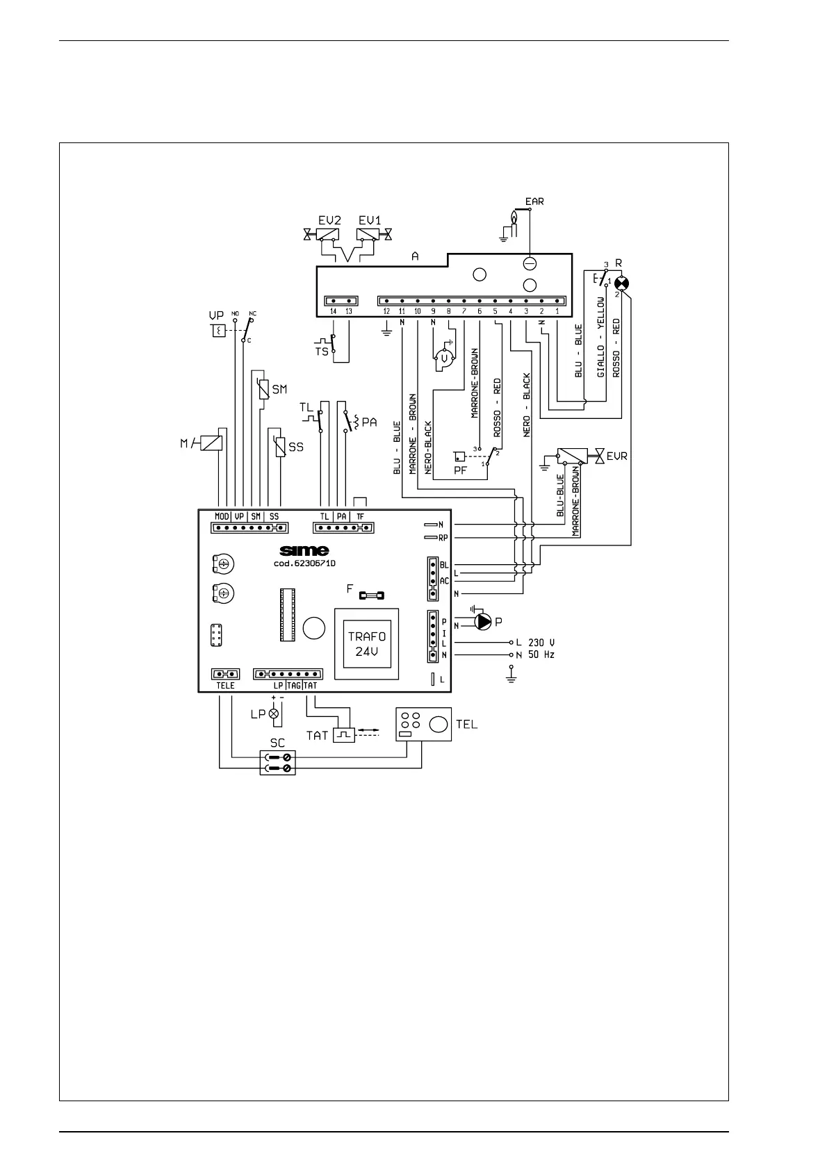
2.8.2 Electrical diagram
KEY
L Line
N Neutral
M Modulator
VP Pressure valve
SM C.H. sensor (blue)
SS D.H.W. sensor (red)
TL Thermostat limiter 85°C
PA Water pressure valve
A Electronic devices
EV1 Electromagnetic valve 1
EV2 Electromagnetic valve 2
EAR Ignition/detection electrode
TS Safety thermostat 100°C
R Device release button
V Ventilator
PF Fumes pressure valve
PF1 Fuse (F 2A)
P Circulator
TEL Remote control
SC Remote control connection
TAT Thermo actuator
LP Indicator light for sufficient
water pressure
EVR Electromagnetic valve for plant filling
CONNECTOR SPARE PARTS CODES:
CN2 cod. 6278687
CN3 cod. 6241414
CN4 cod. 6260940
CN5 cod. 6278685
CN6 cod. 6278686
CN7 cod. 6260969
Fig. 10