65
4.3.1 Valve pressure adjustment
To set the maximum and minimum pressu-
res, proceed as follows (fig. 18):
- Link the column or pressure gauge only
to the tapping point downstream of the
gas valve.
- Disconnect the small pipe from the
VENT of the gas valve (5 fig. 16).
- Remove the cap (1) of the modulator.
- Switch on the boiler and set the sanitary
water on high values.
- Open completely a hot sanitary water
tap.
- Remember that for adjustment, turning
clockwise increases pressure, and anti-
clockwise decreases pressure.
- Adjust the maximum pressure by turning
the nut (3) with a fixed size 10 spanner,
setting pressure at the maximum value
indicated in Table 4.
- Adjust minimum pressure only after
having adjusted maximum pressure.
- Switch off the power supply to the modu-
lator, keep the sanitary water tap open.
- Block the nut (3) and turn the screw (2)
and set pressure at the minimum value
indicated in Table 4.
- Switch the boiler off and on a few times,
always with the hot sanitary water tap
open, and check that the maximum and
minimum pressures correspond to the
established values; if necessary, correct
the adjustment.
-
After regulation, check that the power
supply to the modulator is switched on
again.
- Replace the small pipe on the valve VENT .
- Remove the pressure gauge, taking care
to re-tighten the screw to close the pres-
sure tapping point.
- Replace the plastic cap (1) on the modu-
lator and seal everything, if necessary
with a drop of paint.
4.4 CLEANING AND MAINTENANCE
At the end of every heating season, the boiler
must be inspected and cleaned as follows:
- Switch off power to the boiler and close
the gas supply tap.
- Dismantle the burner-gas manifold group
- For cleaning, direct a jet of air inside the
burners in order to remove any accumu-
lated dust.
-
Then clean the heat exchanger, removing
any dust and any combustion residues. To
clean the heat exchange, and also the bur-
ner, chemical products or steel brushes
must absolutely not be used.
- Ensure that the upper perforated part of
the burners is free of encrustations.
- Replace the components removed from
the boiler, taking care to do so in the cor-
rect order.
- Check functioning of the appliance and of
the main burner. After assembly, the
Fig. 17
KEY
1Cover
2 Minimum pressure regulation screw
3 Maximum pressure regulation nut
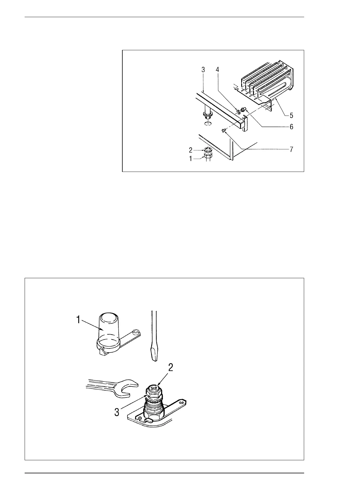
Fig. 18
KEY
1 Ring shake 1/2”
2 Counter nut 1/2”
3 Burner manifold
4 Washer ø 6.1
5 Burners
6 Gas nozzle M6
7 Screw
IMPORTANT: To guarantee
the seal when changing nozz-
les, always use the washer
(4) supplied in the kit, also in
the burner groups for which
it is not foreseen.