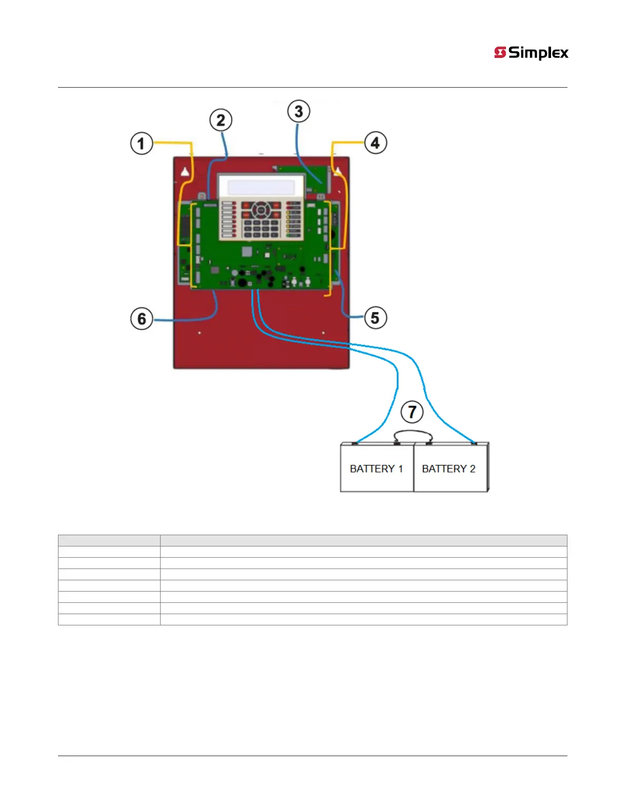
Figure 7: Orange power limited and blue non-power limited wiring
Table provides the description for Figure 7.
Callouts Description
1 PL conduit entry for loop and NAC circuits
2 NPL conduit entry for PSTN lines from the gateway module 12 to 18 AWG.
3 NPL conduit entry for city circuits
4 PL conduit entry for relays, RS485 and Aux power
5 NPL conduit entry for AC power
6 NPL conduit entry for IP channel from gateway module
7 NPL conduit entry for External battery box
Note: Wiring for Internal Battery is NPL and it must be correctly spaced as by the mentioned spacing in section 3.5 with PL wiring while
doing connection.
Caution: When installing, route field wiring away from sharp projections, corners and internal components.
page 13 579-1404 Rev A
2050 and 2250 Foundation Series Fire Alarm Control Units Installation Guide