8. Executive Prom boards and customer label Prom boards are identical; only the Prom chips are unique.
Prom boards can be replaced if the Prom chips are carefully removed and placed in the new Prom
board. Remember that Prom boards must go back in the same position that they came from. If the
customer label or executive Prom chips are bad, new chips will have to be programmed. Each Prom
chip is labeled with its IC socket location as well as the motherboard slot location for the Prom board
on which it is placed.
9. Transmission over the system’s communication lines (both primary and secondary) can be observed
with a Triplett 310 meter. Set your meter on the 12VDC scale. On the console’s l/O panel, locate the
terminal block for the channel you wish to check. If you want to check for communication on the pri-
mary lines, place the black meter lead on the A’Terminal and the red meter lead on the B’Terminal.
Note the meter’s deflection.
No deflection
indicates that the query word is not leaving the Control
Console and that the problem is most likely with the channel’s communication and/or transmission
boards.
One or more distinct deflections
every few seconds indicates that the CPU is transmitting
to the encoders but not receiving a reply. This means that either there is a problem with the communi-
cation lines or the encoders on that channel are not replying.
Rapid Fluctuation
of the meter needle
usually indicates normal communication. This same procedure can be used with the A and B Terminals
for the secondary communication lines.
Note:
On some systems, you may have to reverse your meter leads when checking transmission ov-+ _
the communication lines (black lead on B Terminal and red lead on A Terminal). Also, when
checking for communication on a 4-wire channel, remove the secondary lines from the l/O panel
when checking the primary lines and vice versa.
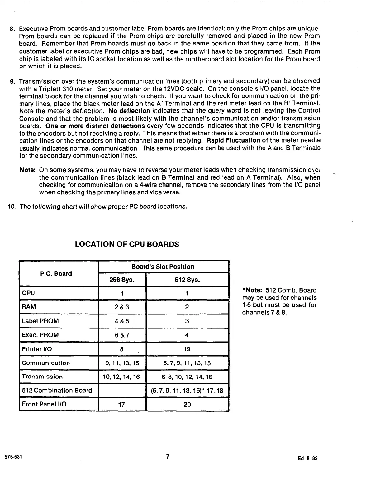
10. The following chart will,show proper PC board locations.
LOCATION OF CPU BOARDS
*Note:
512 Comb. Board
may be used for channels
1-6 but must be used for
channels 7 & 8.
575-531
7
Ed 8 82