8
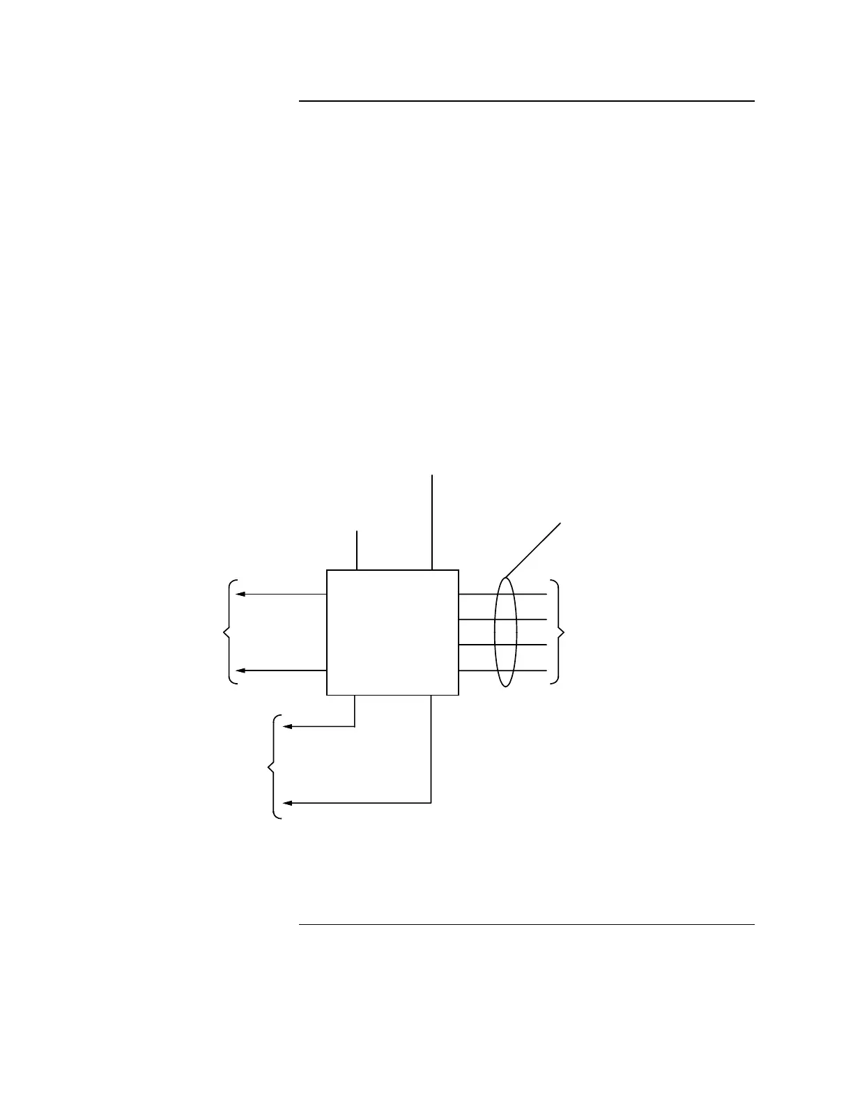
When wiring the 4009, refer to the 841-925 Field Wiring Diagram, the Wiring
Information mounted on the inside of the 4009 panel door, the 4009 NAC Power
Extender Connection Diagram (Figure 4), and the following system wiring
requirements.
• All wiring, except incoming power and ground connecting wires, must be
free from grounds or shorts and have a resistance of one megohm, or higher,
to EARTH.
• All wires are to be copper conductors only.
• All wiring must be terminated with UL listed devices (e.g., wire nuts,
pressure connectors). Wiring terminated with only electrical tape is not
permitted. All splicing (free ends of conductors) must be covered with an
insulation equivalent to that of the conductors.
• When running wires to the 4009, identify the wires appropriately: Input
power, dedicated NAC wiring, external battery connection (if required), and
the four NAC circuits (an additional four NAC circuits are available as a
field-installed option).
4009 NAC
POWER EXTENDER
TO AUDIBLE AND/OR VISIBLE
NOTIFICATION APPLIANCES
(SEPARATE CONTROL OF
STROBES REQUIRES AN
ADDITIONAL FOUR CIRCUIT
MODULE)
NOTIFICATION APPLIANCE CIRCUITS:
FOUR STYLE Y CIRCUITS STANDARD
(STYLE Z CIRCUITS AVAILABLE)
RATED 2A @ 25 VRMS PER CIRCUIT,
POWER LIMITED 8A TOTAL POWER
AVAILABLE
(ADDITIONAL FOUR CIRCUITS AVAILABLE)
EXTERNAL
BATTERY
CONNECTION
(IF REQUIRED)
AC INPUT
POWER
2, #18 AWG MINNAC OF HOST
FACP
CONNECT TO
ADDITIONAL NAC
OF HOST FACP
IF SEPARATE CONTROL
OF ADDITIONAL FOUR
CIRCUIT MODULE IS
REQUIRED
NOTES:
1. REFER TO 841-925 FIELD WIRING DIAGRAM FOR ADDITIONAL INFORMATION.
2. EXTERNAL BATTERY CHARGER REQUIRES SPLICING INTO EXISTING
BATTERY BATTERY HARNESS (733-807) SEE NOTE 1.
(SEE
NOTE 2)
2, #18 AWG MIN
Figure 4. 4009 NAC Power Extender Connection Diagram
Continued on next page
Wiring the 4009
System Installation,
Continued
Technical Manuals Online! - http://www.tech-man.com