EasyManua.ls Logo

Simplex 4009 - User Manual

Simplex 4009
12 pages
To Next Page IconTo Next Page
Loading...
1997 Simplex Time Recorder Co., Gardner, MA 01441-0001 USA
All specifications and other information shown were current as of publication, and are subject to change without notice
574-827
Rev. B
DO NOT INSTALL ANY SIMPLEX PRODUCT THAT APPEARS
DAMAGED.
Upon unpacking your Simplex product, inspect the contents of the
carton for shipping damage. If damage is apparent, immediately file a claim
with the carrier and notify Simplex.
ELECTRICAL HAZARD -
Disconnect electrical power when making any
internal adjustments or repairs. Servicing should be performed by qualified
Simplex Representatives.
STATIC HAZARD -
Static electricity can damage components. Therefore,
handle as follows:
1.
Ground yourself before opening or installing components.
2.
Keep component wrapped in anti-static material at all times.
The Simplex 4009 NAC Power Extender (Figure 1) provides additional DC
signaling capacity to a Fire Alarm Control Panel (FACP) with a reverse polarity
Notification Appliance Circuit (NAC). The 4009 is UL-listed, electrically-
supervised, and protected against brown-out conditions and loss of primary AC
power.
Figure 1. Simplex 4009 NAC Power Extender
Continued on next page
Cautions and Warnings
Introduction
4009 NAC POWER EXTENDER
Technical Manuals Online! - http://www.tech-man.com

Other manuals for Simplex 4009

Question and Answer IconNeed help?

Do you have a question about the Simplex 4009 and is the answer not in the manual?

Simplex 4009 Specifications

General IconGeneral
BrandSimplex
Model4009
CategoryExtender
LanguageEnglish

Summary

Cautions and Warnings

Electrical Hazard Warning

Disconnect electrical power before making internal adjustments or repairs. Servicing should be performed by qualified Simplex Representatives.

Static Hazard Precautions

Ground yourself before opening or installing components. Keep components wrapped in anti-static material at all times.

Introduction to the Simplex 4009 NAC Power Extender

Product Overview

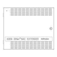
The Simplex 4009 NAC Power Extender provides additional DC signaling capacity to a Fire Alarm Control Panel (FACP).

Functionality and Benefits

Provides 8A signaling power to 4 or 8 NACs, minimizes line losses, and is protected against brown-out and loss of AC power.

Hardware Components

Key Features of the 4009

Supports Style Y/Z NACs, 8A signaling, EARTH fault capability, two-wire operation, and 4001-size back box.

Available Modules

Lists modules like Power Supply (565-367/565-488) and Signal Cards (Style Y/Z, Earth Detect).

Power Supply Details

Explains the linear power supply with brownout/charger features, limited to 18Ah battery charging.

System Configuration

Signal Card Types and Functionality

Describes Style Y (Class B) and Style Z (Class A) Signal Cards for supervision and alarm signaling.

Functional Block Diagram Explanation

Illustrates interconnections between modules, alarm signal, and OV connections for operation and trouble indication.

Alarm Input Requirements

Voltage and Ripple Specifications

Details required input voltage (20-32VDC or 18-32VDC) and maximum ripple for different signal cards.

Alarm Current Limits

Specifies maximum alarm current (2A @ 24VDC) and minimum alarm current (0.9VDC) per Signal Card.

System Installation

General Installation Information

Important notification of personnel and familiarity with material before installation.

Required Tools and Equipment

Lists necessary tools like screwdrivers, voltmeter, wire strippers, and diagrams for installation.

General Installation Notes

Adherence to local codes, conductor length, service loops, physical protection, and neat wiring for inspection.

Installation Checklist Procedure

A systematic checklist for mounting, wiring, connecting power, batteries, and testing the system.

Mounting the 4009 Unit

Step-by-step instructions for opening, preparing, and physically mounting the 4009 back box on a wall.

Wiring the 4009 Unit

Details wiring standards, wire types, termination methods, and wire identification for input power, NAC, and battery.

Mounting and Wiring Peripheral Devices

Procedures for determining mounting locations, installing devices, and connecting wires for Style Y/Z circuits.

System Wiring Configurations

Lists various wiring configurations like Style Y/Z, single/two signal cards, and reverse polarity devices.

Jumper Placements and Terminal Connections

Details jumper placements (P3, P4) and terminal block connections (TB1, TB2) for signal cards and power supplies.

Related product manuals