9
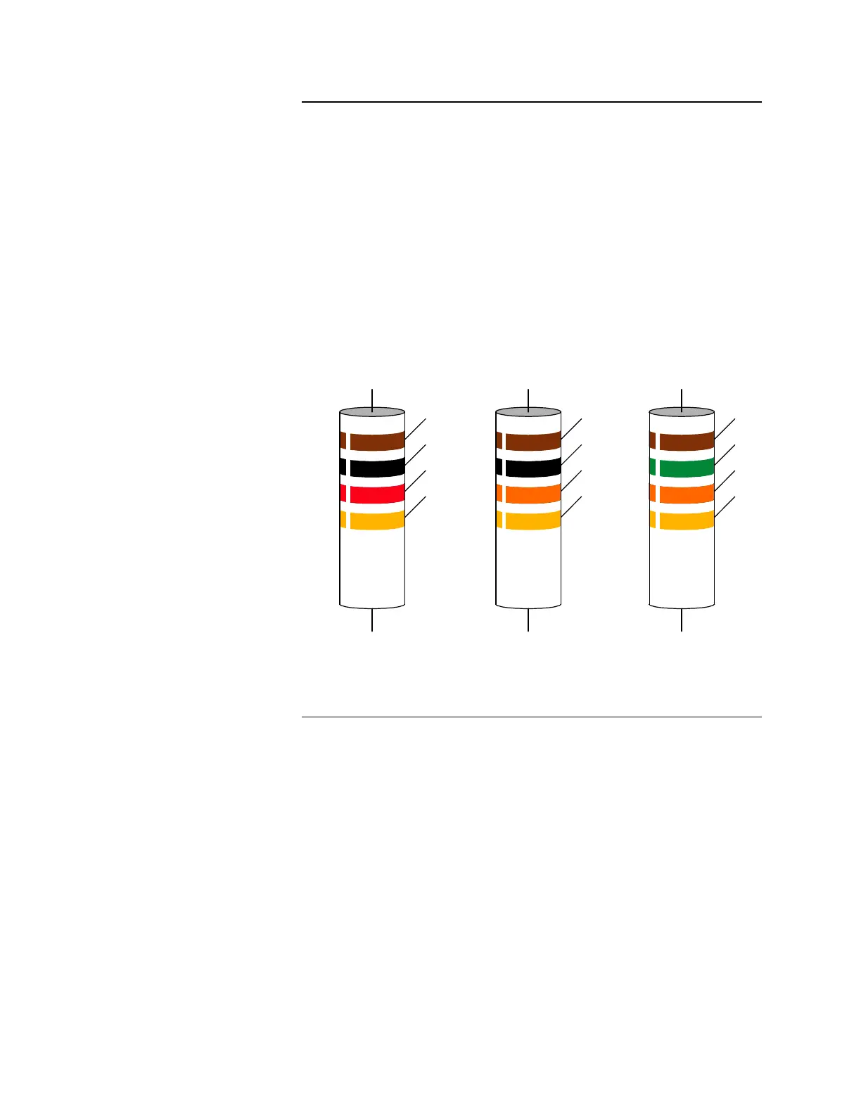
Note: Use the resistor color code shown in Figure 5 to identify the End-of-
Line Resistors used in the installation.
Refer to the 841-925 Field Wiring Diagram and the procedure listed below when
installing the 4009 peripheral devices.
1. Determine the mounting locations of the peripheral devices and install
system wires from the mounting location of each peripheral device to the
565-386 or 565-569 Style Y (Class B) Signal Card or the 565-388 or 565-
545 Style Z (Class A) Signal Card.
2. Install all peripheral devices and connect them to appropriate wires. (Refer
to the installation instructions packed with the devices.)
3. For Style Y (Class B) devices, connect a 10K, 1/2 W End-of-Line Resistor
(EOLR) across the terminals of the last device in the circuit and mark the
device accordingly.
Figure 5. End-of-Line Resistor (EOLR) Color Code
Continued on next page
Mounting and Wiring
Peripheral Devices
BROWN
BLACK
RED
GOLD
BROWN
BLACK
ORANGE
GOLD
1,000-OHM (1K, 1/2 WATT)
RESISTOR
10,000-OHM (10K, 1/2 WATT)
RESISTOR
BROWN
GREEN
ORANGE
GOLD
15,000-OHM (15K, 1/2 WATT)
RESISTOR
System Installation,
Continued
Technical Manuals Online! - http://www.tech-man.com