Operator Interface Features
Convenient and extensive operator information is
provided using a logical, menu-driven display
Multiple automatic and manual diagnostics for
maintenance reduction
Convenient PC programmer label editing
Password access control
Alarm and Trouble History Logs (up to 2000 total
events) are available for viewing from the LCD, or
capable of being printed to a connected printer, or
downloaded to a service computer
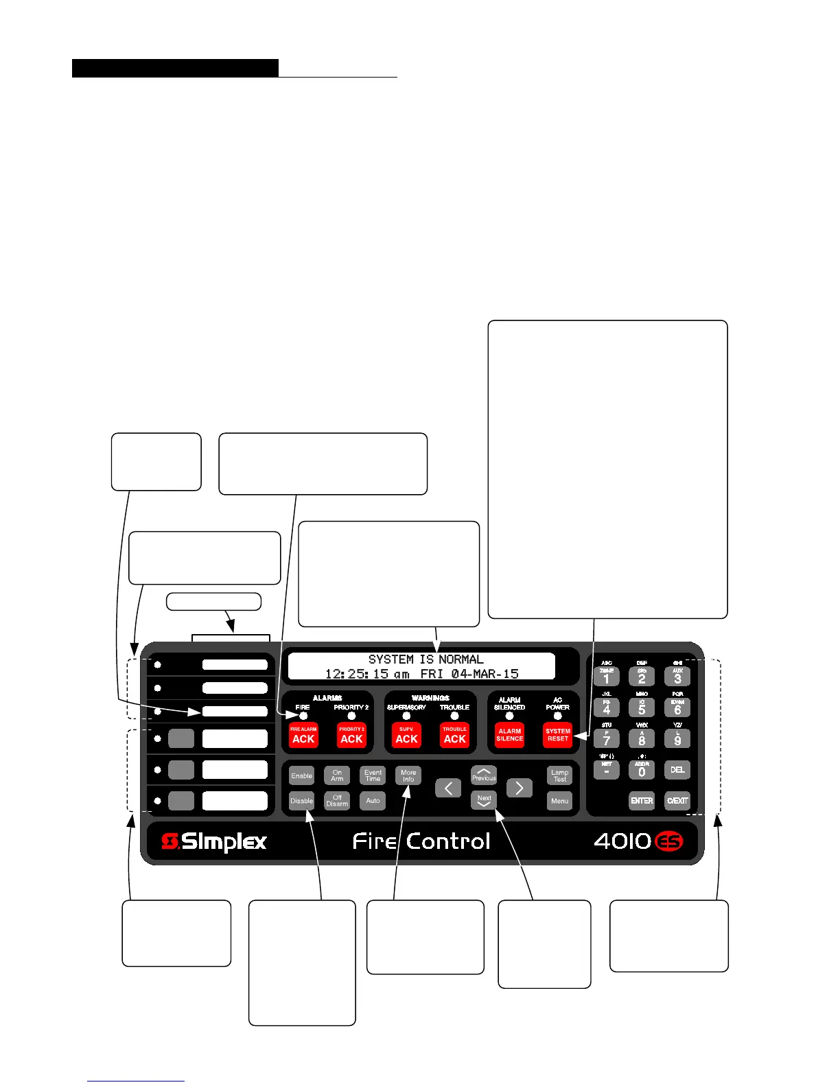
Convenient Status Information. With the locking
door closed, the glass window allows viewing of the
display, status LEDs, and available operator switches.
Features include a two-line by 40-character, wide viewing
angle (super-twist) LCD with status LEDs and switches as
shown in the illustration below.
LED indicators describe the general category of activity
being displayed with the LCD providing more detail. For
the authorized user, unlocking the door provides access to
the control switches and allows further inquiry by
scrolling the display for additional detail.
The following illustration identifies the primary functions
of the operator interface.
6 SYSTEM STATUS INDICATOR LEDs provide
system status indications, LEDs flash to indicate
a change in status and remain on-steady after
acknowledged until reset
3 PROGRAMMABLE
FUNCTION SWITCHES
with yellow LED
indicators
POINT STATUS
CONTROL KEYS:
Point Enable and
Disable
Force On or Arm
Force Off or Disarm
Return On/Off or
Arm/Disarm to Auto
Mode
NUMERIC KEYPAD for
point category and point
selection (alphabet
characters are not used at
this time)
ADDITIONAL FUNCTION
KEYS:
Event Time Request
More Information Request
Lamp Test
Elevator Bypass
City Disconnect
Ground Fault
Waterflow-West
Waterflow-East
Custom label insert
LCD NAVIGATION
CONTROL:
Menu selection
Vertical and
Horizontal position
selection buttons
2 X 40 LCD READOUT, LCD is
backlighted during normal conditions,
provides up to 40 characters for custom
label information
FIRST ALARM DISPLAY operation can
be selected for maintained display of first
alarm until acknowledged
3 PROGRAMMABLE LEDs
two selectable as Red or Yellow,
one selectable as Green or Yellow
Ground Fault
Latch
FIRE ALARM ACK acknowledges a Fire Alarm
condition, logs the acknowledge, and silences the
operator panel and all annunciator tone-alerts
PRIORITY 2 ACK acknowledges a Priority 2 Alarm
condition, logs the acknowledge, and silences the
operator panel and all annunciator tone-alerts
SUPV ACK acknowledges system supervisory
conditions, logs the acknowledge, and silences the
operator panel and all annunciator tone-alerts
TROUBLE ACK acknowledges system trouble
conditions, logs the acknowledge, and silences the
operator panel and all annunciator tone-alerts
ALARM SILENCE causes audible notification
appliances to be silenced (depending on panel
programming) typically after evacuation is complete and
while alarm source is being investigated; may allow
visible notification to continue (strobes still flashing)
SYSTEM RESET restores control panel to normal when
all alarmed inputs are returned to normal
ULC SYSTEMS
require designating
a Ground Fault
indicator
3 S4010-0011-5 11/2015
 Loading...