11
IMPORTANT: The 4100-3201, -3202, and -3203 Relay Modules are non-power
limited modules that cannot be placed inside the master controller bay unless the
proper wire separation can be achieved and maintained (per UL864).
Up to two 2” motherboards may be installed with the system CPU in the master controller bay.
Note that only one 4100-3203 can fit in the master controller bay, because the 4100-3203
motherboard takes up 4”.
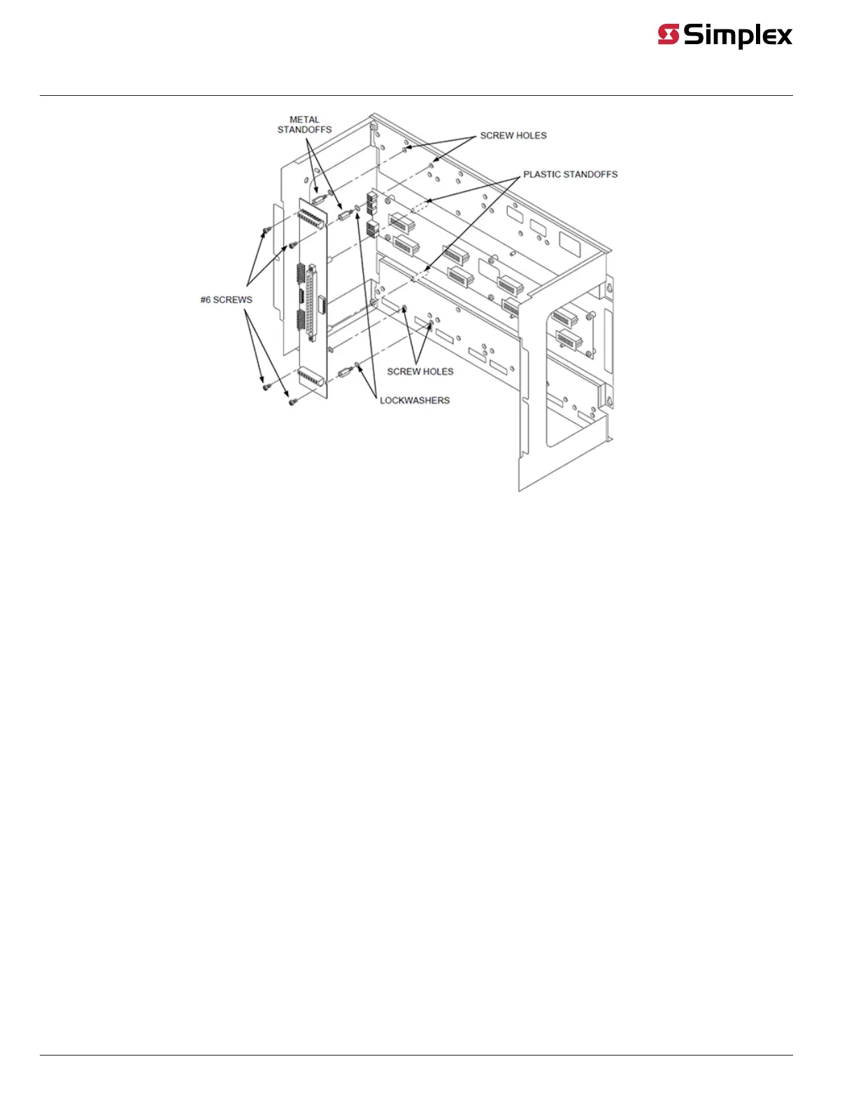
Use the following directions to mount a motherboard into a CPU bay.
1. Orient the motherboard with the connector labeled J1 on the right and the header labeled
P1 on the left.
2. Slide the motherboard to the right until the pins from P1 on the motherboard to the right
are completely inserted in the motherboard’s J1 connector.
3. Attach four lockwashers and metal standoffs to the chassis, and secure the motherboard
to the chassis using four #6 screws.
Figure 6. Installing the Motherboard into a 4100U/4100ES CPU Bay
Continued on next page
Installing Boards into 2975-94xx Back Boxes (4100U/4100ES), Continued
Installing 4100-3201
to -3203
Motherboards into a
2975-94xx Master
Controller Bay
J1
Slide the motherboard to the right until P1 on the first
motherboard connects with J1 on the next one.
Master Controller
Motherboard
SPS
P1
The 4120-3202
motherboard takes up
two slots.