10
The relay modules can be mounted to either 4100 Back Boxes (PID series 2975-91xx) or
4100U/4100ES Back Boxes (PID series 2975-94xx) as follows:
• The 4120-3001, -3002, and -3003 are used for systems with 4100 Back Boxes.
• The 4100-3201 through -3204 and -3206 are used for systems with 4100U/4100ES Back Boxes.
This section describes mounting the 4100-3201 through -3204 and -3206 into 4100U/4100ES
Back Boxes.
For instructions on mounting the 4010-9908 into a 4010ES back box, see “Installing Boards into
4010ES Back Boxes” in this document.
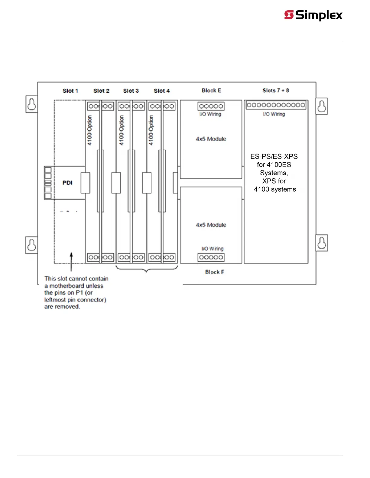
The 4100-3204 and -3206 Relay Cards are designed to be mounted on the PDI in a 4100U/4100ES
expansion cabinet. The card can be mounted on any of the PDI connectors.
Use connector P1, labeled on the back side of the card, to connect to any of the eight PDI
connectors as shown in Figure 5, below.
Figure 5. 4100-3204 and -3206 Mounting
Continued on next page
Installing Boards into 2975-94xx Back Boxes (4100U/4100ES)
Overview
Installing 4100-3204
and -3206 Cards
FUSE COVER
STANDOFFS
#6 SCREWS
WASHERS
PDI CONNECTOR
(reverse side)
PDI
STANDOFFS