21
Note: The information in this section is also applicable to the 4010-9908 4-Point AUX
Relay Card (4010ES)
The 4100-3204 Relay Module includes 4 relays, each rated at 2 A. Each relay controls two sets of
contacts and a separate 3 A fuse protects each set of contacts. Four unsupervised feedback
circuits, which are typically used to determine the state of a separate set of contacts (such as the
sail switch on a damper), are also provided. For battery calculation purposes, the module draws 18
mA in the normal supervisory condition and 70 mA with the relays activated.
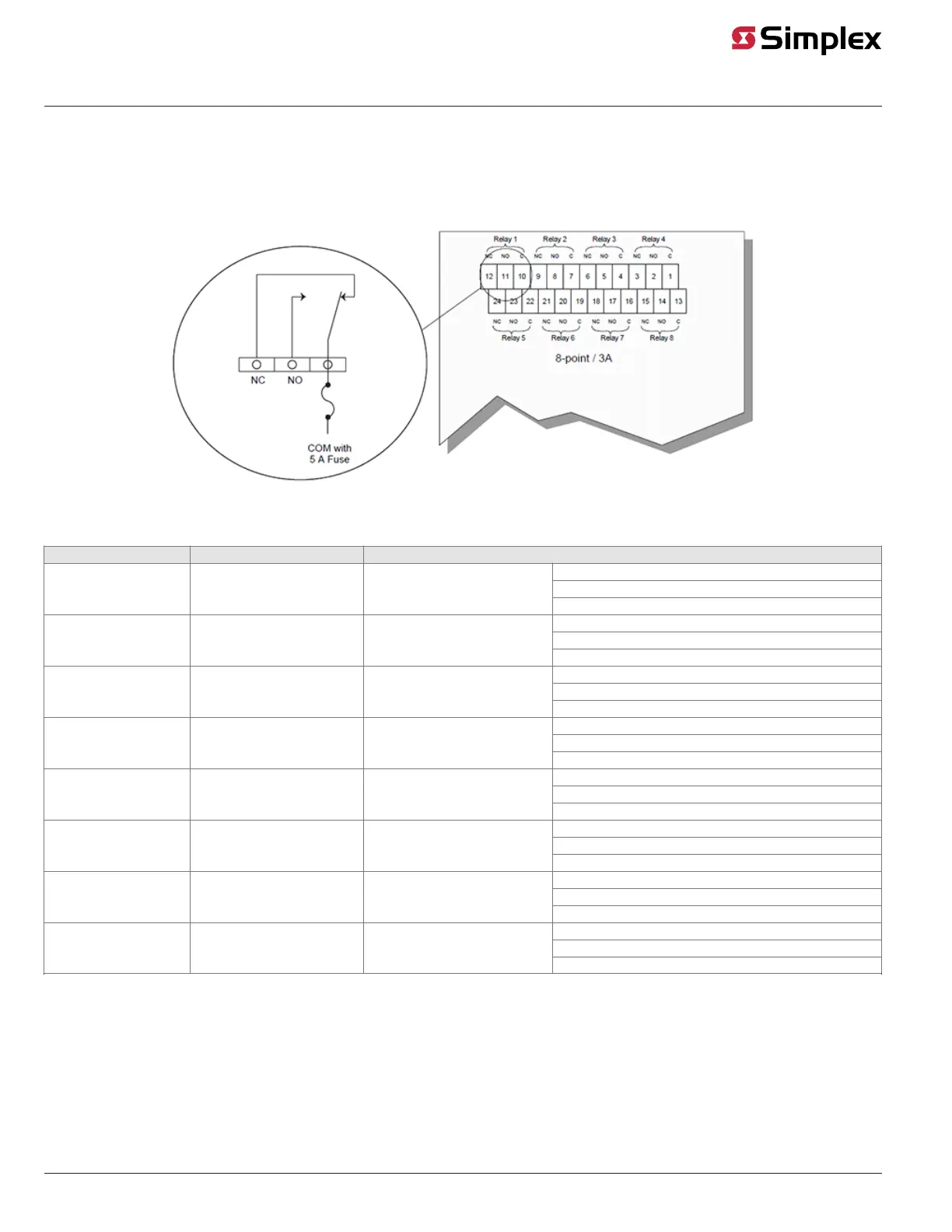
All contacts are Form C, dry contacts, meaning the Common terminal is connected to the
Normally Closed terminal when the relay’s coil is in the de-energized state. The card’s 30 VDC
load capacity is 2 A* resistive/0.5 A inductive, and its 120 VAC load capacity is 0.5 A resistive/
0.5 A inductive. The feedback circuits are rated at 24 VDC, 850 uA maximum short circuit
current, with maximum line resistance of 100 Ohms. The feedback circuit is power-limited and
intended for connection to contacts only. If the relay contacts are not switching power from the
MSS (4010ES),UPS, SPS, XPS, RPS, or 4100-1108 power supply, or a power-limited power
supply that is UL-listed for fire protective signaling use, the feedback circuits are non-power-
limited. Refer to Figure 13 for the designations of the contacts and feedback circuits.
Figure 13. 4100-3204 Relay Module Wiring
*Also 2 A at 30 VAC, non-inductive.
Continued on next page
4
+ FB1
- FB1
+ FB2
- FB2
FB3 +
FB3 -
FB4 +
FB4 -
4-point / 2A
Relay 1a Relay 1b Relay 2a Relay 2b
NC NO C NC NO C NC NO C NC NO C
NC NO C NC NO C NC NO C NC NO C
Relay 3a Relay 3b Relay 4a Relay 4b
16 15 14 13 12 11 10 9 8 7 6 5
32 31 30 29 28 27 26 25 24 23 22 21
4 3 2 1
20 19 18 17
Relay 1a Relay 1b
NC NO C NC NO C
16 15 14 13 12 11
3A
Fuse
3A
Fuse
Wiring, Continued
4100-3204 Wiring
Relay Fuse Contacts
K1
F1 RELAY 1A
TB1-16 NC
TB1-15 NO
TB1-14 C
F2 RELAY 1B
TB1-13 NC
TB1-12 NO
TB1-11 C
K2
F3 RELAY 2A
TB1-10 NC
TB1-9 NO
TB1-8 C
F4 RELAY 2B
TB1-7 NC
TB1-6 NO
TB1-5 C
K3
F5 RELAY 3A
TB1-32 NC
TB1-31 NO
TB1-30 C
F6 RELAY 3B
TB1-29 NC
TB1-28 NO
TB1-27 C
K4
F7 RELAY 4A
TB1-26 NC
TB1-25 NO
TB1-24 C
F8 RELAY 4B
TB1-23 NC
TB1-22 NO
COM with
3 A Fuse
COM with
3 A Fuse
NC NO NC NO