22
Relay Fuse Contacts
K1 F1 RELAY 1
TB1-12 NC
TB1-11 NO
TB1-10 C
K2 F2 RELAY 2
TB1-9 NC
TB1-8 NO
TB1-7 C
K3 F3 RELAY 3
TB1-6 NC
TB1-5 NO
TB1-4 C
K4 F4 RELAY 4
TB1-3 NC
TB1-2 NO
TB1-1 C
K5 F5 RELAY 5
TB1-24 NC
TB1-23 NO
TB1-22 C
K6 F6 RELAY 6
TB1-21 NC
TB1-20 NO
TB1-19 C
K7 F7 RELAY 7
TB1-18 NC
TB1-17 NO
TB1-16 C
K8 F8 RELAY 8
TB1-15 NC
TB1-14 NO
TB1-13 C
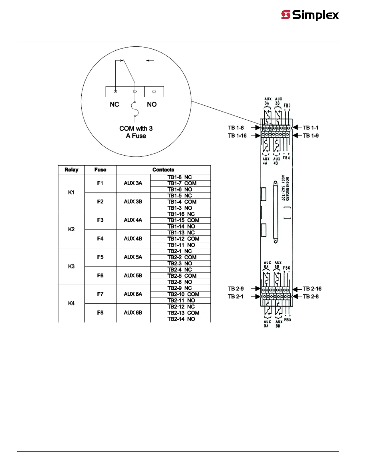
The 4100-3206 Relay Module includes 8 relays, each rated at 3 A. Each relay controls a set of
contacts and a separate 5 A fuse protects each set of contacts. For battery calculation purposes,
the module draws 16 mA in the normal supervisory condition and 200 mA with the relays
activated.
All contacts are Form C, dry contacts, meaning the Common terminal is connected to the
Normally Closed terminal when the relay’s coil is in the de-energized state. The card’s 30 VDC
and 120 VAC load capacity is 3 A resistive/1.5 A inductive. Refer to Figure 14 for the
designations of the contacts and feedback circuits.
Figure 14. 4100-3206 Relay Module Wiring
Continued on next page
8-point / 3A
Relay 1 Relay 2 Relay 3 Relay 4
Relay 5 Relay 6 Relay 7 Relay 8
NC NO C NC NO C NC NO C NC NO C
NC NO C NC NO C NC NO C NC NO C
12 11 10 9 8 7 6 5 4 3 2 1
24 23 22 21 20 19 18 17 16 15 14 13
Relay 1
NC NO C
12 11 10
5A
Fuse
Wiring, Continued
4100-3206 Wiring
COM with
5 A Fuse
NC NO