23
The 4120-3001 and 4100-3201 Relay Modules ⎯ both of which consist of the 562-760 Daughter
Card and the 562-727 Motherboard ⎯ include four relays, each rated at 2 amps. Each relay
controls two sets of contacts and a separate 3 A fuse protects each set of contacts. Four feedback
circuits, which are typically used to determine the state of a separate set of contacts (such as the
sail switch on a damper), are also provided.
All contacts are Form C, dry contacts, meaning the Common terminal is connected to the
Normally Closed terminal when the relay’s coil is in the de-energized state. The maximum load
that can be wired to the contacts is 2 A at 30 VDC. These relays are not rated for AC power.
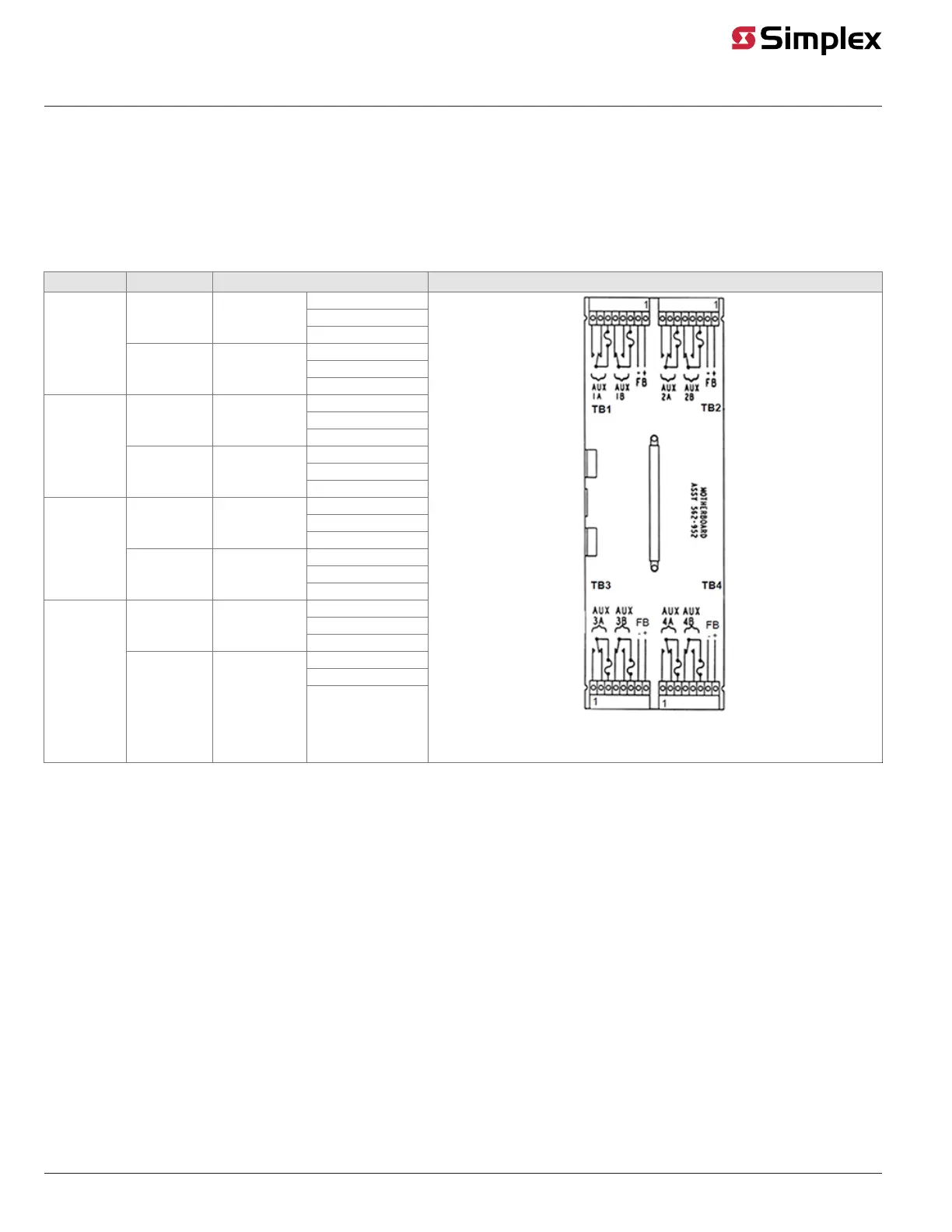
Refer to Figure 15 for the designations of the contacts and feedback circuits. All wiring
connections are made to the 562-727 Motherboard.
Figure 15. Wiring Connections for 4100/4120-3001 and 4100-3201 Relay Modules
Continued on next page
Wiring, Continued
4 Relay / 2 Amp
Module