24
The 4120-3002 and 4100-3202 Relay Modules ⎯ both of which consist of the 562-952 Daughter
Card and the 562-951 Motherboard ⎯ include four relays, each rated at 10 A at 30 VDC or 10 A
at 120/240 VAC. Each relay controls two sets of contacts and a separate 15 A fuse protects each
set of contacts. Four feedback circuits, which are typically used to determine the state of a
separate set of contacts (such as a set of contacts on a motor), are also provided.
All contacts are Form C, dry contacts, meaning the Common terminal is connected to the
Normally Closed terminal when the relay’s coil is in the de-energized state. The maximum load
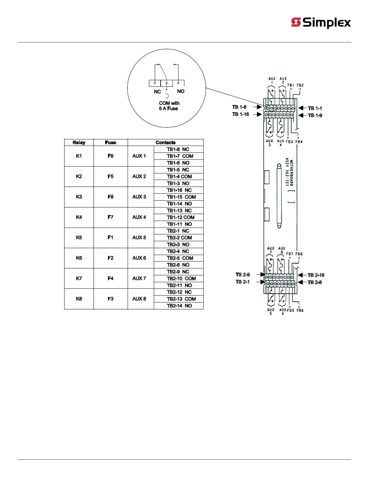
that can be wired to the contacts is 10 A. Refer to Figure 16 for the designations of the contacts
and feedback circuits. All wiring connections are made to the 562-952 Motherboard. The NO,
NC, and COM designations are silkscreened on the motherboard.
Figure 16. Wiring Connections for 4100/4120-3002 and 4100-3202 Relay Modules
Continued on next page
Wiring,
Continued
4 Relay / 10 Amp
Module
Relay Fuse Contacts
K1
F1 AUX 1A
TB1-8 NO
TB1-7 NC
TB1-6 COM
F2 AUX 1B
TB1-5 NC
TB1-4 NO
TB1-3 COM
K2
F3 AUX 2A
TB2-8 NO
TB2-7 NC
TB2-6 COM
F4 AUX 2B
TB2-5 NC
TB2-4 NO
TB2-3 COM
K3
F5 AUX 3A
TB3-1 NO
TB3-2 NC
TB3-3 COM
F6 AUX 3B
TB3-4 NC
TB3-5 NO
TB3-6 COM
K4
F7 AUX 4A
TB4-1 NO
TB4-2 NC
TB4-3 COM
F8 AUX 4B
TB4-4 NC
TB4-5 NO
TB4-6 COM
FB
- +
FB
- +
TB1
TB2
TB3 TB4
1 1
1
1