IDNet LEDs and Addressing
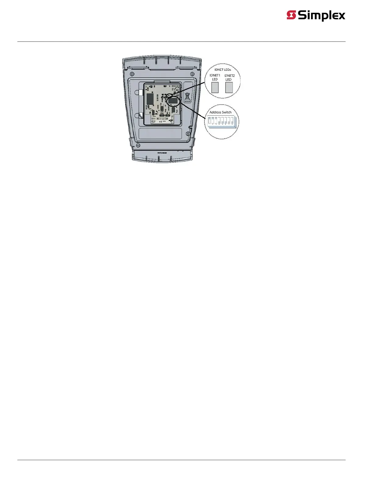
Figure 2: LED and Address Switch Location
LEDs:
Remove the Beam Detector’s cover to access the LEDs.
• IDNET1: This red LED corresponds to the head connected to DET1 on the device. When lit, it indicates a trouble or an alarm on the DET1
channel.
• IDNET2: This red LED corresponds to the head connected to DET2 on the device. When lit, it indicates a trouble or an alarm on the DET2
channel.
Addressing:
This device has a unique address that is set via an eight-position DIP switch. Position 1 is the least significant bit (LSB) and position 8 is the most
significant bit (MSB).
To set the address:
1. Retrieve the address from the ES Programmer. Use the first address assigned by the programmer if multiple addresses are required for the
device (see Programming and Editing the device point).
2. Use a small screwdriver or pen to set the switches to the address.
3. Record the set address.
page 3 579-1039 Rev. D
4098-9019 IDNet Addressable Beam Detector Wiring and FACP Programming