EasyManua.ls Logo

Simplex 4099-9032 - User Manual

Simplex 4099-9032
2 pages
Print Icon
To Next Page IconTo Next Page
Loading...
4099-9032 through 4099-9037
IDNet Manual Call Point
Installation Instructions
1998 Simplex Time Recorder Co., Gardner, MA 01441-0001 USA
All specifications and other information shown were current as of publication, and are subject to change without notice.
574-787
Rev. A
Cautions and Warnings
ELECTRICAL HAZARD -
Disconnect electrical power when installing or servicing.
STATIC HAZARD -
Static electricity can damage components. Ground yourself before opening or installing
components.
Introduction
The 4099-9032 through 4099-9037 Series Manual Call Points provide a means to manually initiate a fire alarm
condition to the 4010 Fire Alarm Control Panel (FACP), via the IDNet™ channel. The IDNet channel provides the
communication link between a call point and 4010 FACP and powers the entire circuitry.
Installation
Addressable call point installation consists of the following steps.
1.
Setting the call point address.
2.
Making electrical connections to the call point.
3.
Mechanically installing the call point.
4.
Replacing the glass substitute element with the break glass.
5.
Testing the call point.
1. Setting the Call Point Address
Each call point has a unique address (1 through 250). The address of the call point is set via an eight position DIP
switch (Figure 2), DIP switch position 1 is the least significant bit (LSB) and position 8 is the most significant bit
(MSB). Set the call point address using Figure 2 as a reference. Use a small screwdriver or pen to set the switches.
Configure the call point to the 4010 panel using the 4010 Fire Alarm Panel Programming Instructions (574-054) and
the 4010 Fire Alarm Installation and Operation Instructions (574-052). Use device type KACPUL. Refer to the
4010 Panel Label (526-444) for the appropriate revision of the instructions to be used.
0000 1000 0100 1100 0010 1010 0110 1110 0001 1001 0101 1101 0011 1011 0111 1111
0000
0 16 32 48 64 80 96 112 128 144 160 176 192 208 224 240
1000
1 17 33 49 65 81 97 113 129 145 161 177 193 209 225 241
0100
2 18 34 50 66 82 98 114 130 146 162 178 194 210 226 242
1100
3 19 35 51 67 83 99 115 131 147 163 179 195 211 227 243
0010
4 20 36 52 68 84 100 116 132 148 164 180 196 212 228 244
1010
5 21 37 53 69 85 101 117 133 149 165 181 197 213 229 245
0110
6 22 38 54 70 86 102 118 134 150 166 182 198 214 230 246
1110
7 23 39 55 71 87 103 119 135 151 167 183 199 215 231 247
0001
8 24 40 56 72 88 104 120 136 152 168 184 200 216 232 248
1001
9 25 41 57 73 89 105 121 137 153 169 185 201 217 233 249
0101
10 26 42 58 74 90 106 122 138 154 170 186 202 218 234 250
1101
11 27 43 59 75 91 107 123 139 155 171 187 203 219 235
0011
12 28 44 60 76 92 108 124 140 156 172 188 204 220 236
1011
13 29 45 61 77 93 109 125 141 157 173 189 205 221 237
0111
14 30 46 62 78 94 110 126 142 158 174 190 206 222 238
15 31 47 63 79 95 111 127 143 159 175 191 207 223 239
LSB MSB
1 2345678
1111
DIP SWITCHES 5 THRU 8
ON
OFF
1 = ON 0 = OFF
251
252
253
254
255
DIPSWITCH IS SHOWN SET AT ADDRESS 7.
Note:
DIP switch in “1” position is
“ON” while DIP switch in “0”
position is “OFF.”
Figure 3. Call Point Addressing ChartFigure 2. Rear View of Call Point
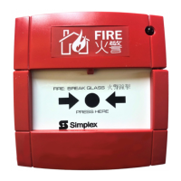
Figure 1. Front View of Call Point
(English Version with Glass Installed)
Red IDNet +
Black IDNet -
DIP Switches
Question and Answer IconNeed help?

Do you have a question about the Simplex 4099-9032 and is the answer not in the manual?

Overview

The Simplex 4099-9032 through 4099-9037 Series IDNet Manual Call Point is a device designed to manually initiate a fire alarm condition within a fire alarm system. It communicates with a 4010 Fire Alarm Control Panel (FACP) via the IDNet™ channel, which also provides power to the call point's circuitry.

Function Description:

The primary function of this device is to allow occupants to manually trigger a fire alarm. When activated, it sends a signal to the FACP, indicating a fire condition at its specific address.

Important Technical Specifications:

  • Compatibility: Designed for use with the 4010 Fire Alarm Control Panel (FACP).
  • Communication: Utilizes the IDNet™ channel for communication and power.
  • Addressing: Each call point has a unique address (1 through 250), set via an eight-position DIP switch. DIP switch position 1 is the least significant bit (LSB), and position 8 is the most significant bit (MSB). The addressing chart provided in the manual details the DIP switch settings for each address.
  • Wiring: Connects to the IDNet channel using red (IDNet +) and black (IDNet -) wires. Field wiring connections must comply with local codes.
  • Wiring Distance: The maximum allowable run from the 4010 FACP to the farthest device is 2,500 feet. The maximum total wire length (including all T-Taps) from the 4010 FACP is 10,000 feet.
  • Power: IDNet wiring is supervised and power-limited.
  • Mounting: Designed to be installed into a suitable electrical box (not supplied). It fits directly to a U.K. switch/socket box, with a minimum box depth of 25mm recommended. Various mounting accessories are available, including:
    • 4099-9811 Terminal Tray for flush mounting (used in Europe, except Italy and France, and Asian Countries).
    • 4099-9812 Terminal Tray with Bezel for flush mounting (used in USA, Canada, Australia, Italy, and South Africa).
    • 2975-9220 Plastic Box for surface mounting (universal use).
  • Device Type: When configuring the call point to the 4010 panel, the device type KACPUL should be used.

Usage Features:

  • Manual Activation: Provides a clear and accessible means for manual fire alarm initiation.
  • Addressability: Each call point is individually addressable, allowing the FACP to pinpoint the exact location of the alarm.
  • DIP Switch Configuration: Addresses are easily set using an eight-position DIP switch, requiring a small screwdriver or pen.
  • Glass Element: The call point is designed to incorporate a break glass element, which must be installed by the user, replacing a plastic substitute element shipped with the device. This provides a clear visual and tactile indication of activation.
  • English Version: The device is available in an English version with glass installed, as depicted in the manual.

Maintenance Features:

  • Testing Capability: A key is provided with the call point for testing without breaking the glass. By inserting the key into a small keyhole on the bottom left of the call point, the glass (or substitute) drops, activating the switch for testing purposes. It is crucial not to leave the test key with the call point after commissioning.
  • Component Replacement: The glass substitute element can be replaced with the break glass element by removing a screw, taking out the plastic element, inserting the break glass, and re-securing the cover.
  • Installation Instructions: Comprehensive instructions are provided for setting the address, making electrical connections, mechanically installing the call point, replacing the glass substitute element, and testing the call point.
  • Safety Warnings: The manual includes important safety warnings regarding electrical hazards (disconnect power before servicing) and static hazards (ground yourself before opening or installing components) to ensure safe handling and maintenance.
  • Documentation: References to the 4010 Fire Alarm Panel Programming Instructions (574-054), 4010 Fire Alarm Installation and Operation Instructions (574-052), and 4010 Panel Label (526-444) are provided for comprehensive system configuration and operation.

Simplex 4099-9032 Specifications

General IconGeneral
BrandSimplex
Model4099-9032
CategoryFire Alarms
LanguageEnglish

Related product manuals