2. Slide the motherboard you are installing to the left until the pins are completely inserted in the connector of a previously installed motherboard.
3. Secure the motherboard to the chassis with four torx screws.
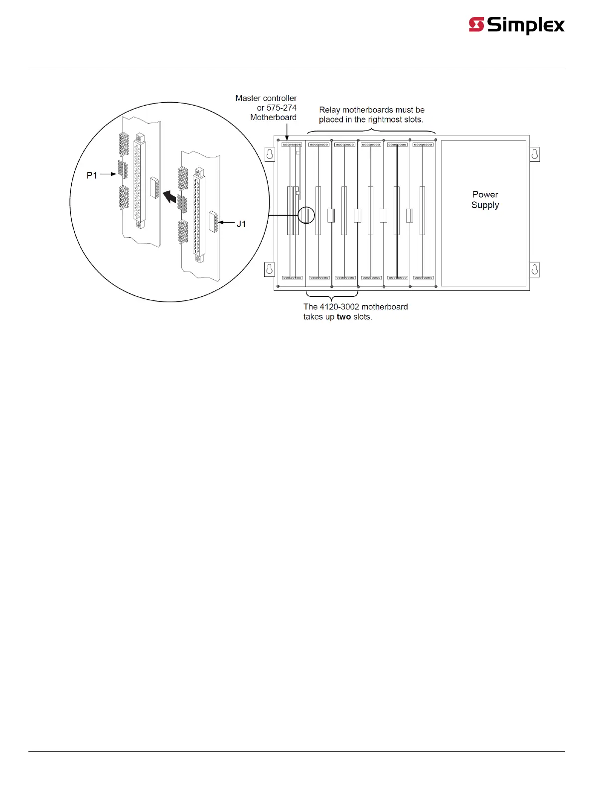
Figure 3: Installing the Motherboard into a 4100 Master Controller Bay
Installing into a 2975-91xx Expansion Bay
Review the following guidelines before mounting the motherboard into a 2975-91xx Expansion Bay.
• If a power supply is installed in the bay, it must be installed on the far right of the bay and any relay modules must be installed in the slots
immediately to its left.
• Relay cards must be installed in the rightmost possible slots. This is necessary to allow for the proper routing of non-power limited wiring
(typically 120 VAC wiring), which could be connected to a relay module.
• If a 4100/4120-0155 SDACT, 4100-6052 Event Reporting DACT, 4100-6053 Point Reporting DACT, or a 4100/4120-0153 CCDACT is installed
in the bay, it must be installed in the far left or far right slot. Neither of these modules contains the J1 or P1 connectors, which are used to
distribute power and communications to adjacent modules.
Use the following directions and Figure 3 to install a motherboard into an expansion bay.
1. Orient the motherboard with the connector labeled J1 on the right and the header labeled P1 on the left.
2. Match the connector on the previously installed motherboard with the pins on the motherboard you are installing. Slide the motherboard to the
left until the pins are completely inserted in the connector of the previously installed motherboard. If you are installing the leftmost board, the
pins will remain unconnected.
3. Secure the motherboard to the chassis with four torx screws.
page 5 579-220 Rev. F
4100/4120- Series and 4010ES Relay Modules Installation Instructions
 Loading...