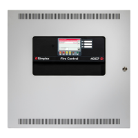
Figure 7: Installing the Motherboard into a 4100ES CPU Bay
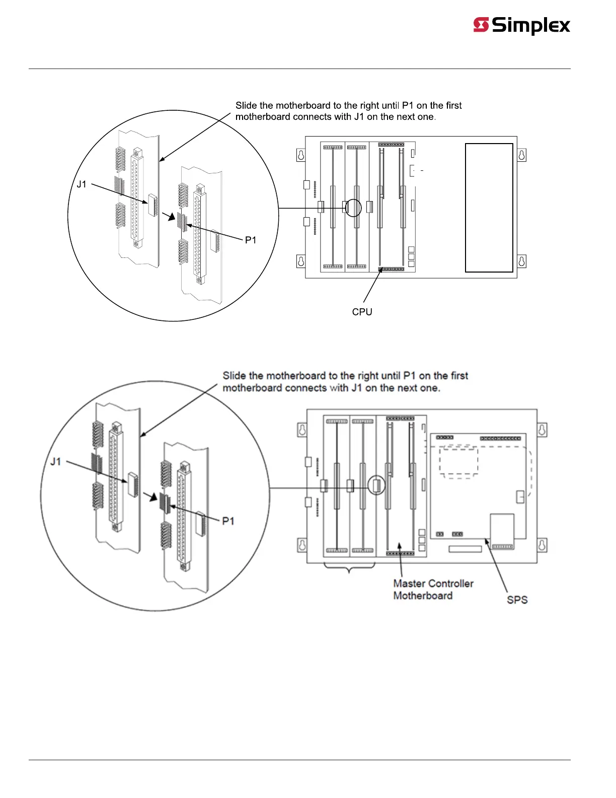
Figure 8: Installing the Motherboard into a 4100U CPU Bay
Note: The 4120-3202 motherboard takes up two slots.
Installing 4100-3201 to 4100-3203 Motherboards into a 2975-94xx Expansion Bay
When installing motherboards in a 4100U/4100ES expansion bay, adhere to the following guidelines:
• Each expansion bay assembly includes a chassis, two end supports, one LED/switch frame, and a power distribution interface (PDI) board.
• An expansion bay holds up to eight 4" x 5" modules. A double-size module, such as the ES-XPS, ES-PS, or XPS in legacy systems, takes up two
blocks of space as shown below.
• Up to seven 2" x 11 ½" motherboards or three 4" x 11 ½" motherboards can be installed in an expansion bay if no 4" x 5" modules are installed
in the bay. Motherboards are mounted on top of the PDI in expansion bays. The data and power that would normally be bussed via the PDI is
instead routed across the boards via ribbon cable from one board to the next.
page 9 579-220 Rev. F
4100/4120- Series and 4010ES Relay Modules Installation Instructions
 Loading...