Setting the Address
1. The MX Digital Loop Card Address is set through a Dual-In-Line Package (DIP)
switch SW100, which is a bank of eight switches. From left to right these switches
are designated as SW100-1 through SW100-8 (see Figure 4). Their functions are as
follows:
• SW100-1: This switch sets the baud rate for the internal communications line running
between the MX Digital Loop card and the CPU. Set this switch to ON.
• SW100-2 through SW100-8: These switches set the card address within the Fire Alarm
Control Panel (FACP). Refer to Table 2 for a complete list of switch settings for all of
the possible module addresses.
Note: Set these switches to the value assigned to the MX Digital Loop card by
the 4100ES Programmer.
Setting the
MX Loop Card
Address
Step 2: Configuring the MX Digital Loop Card
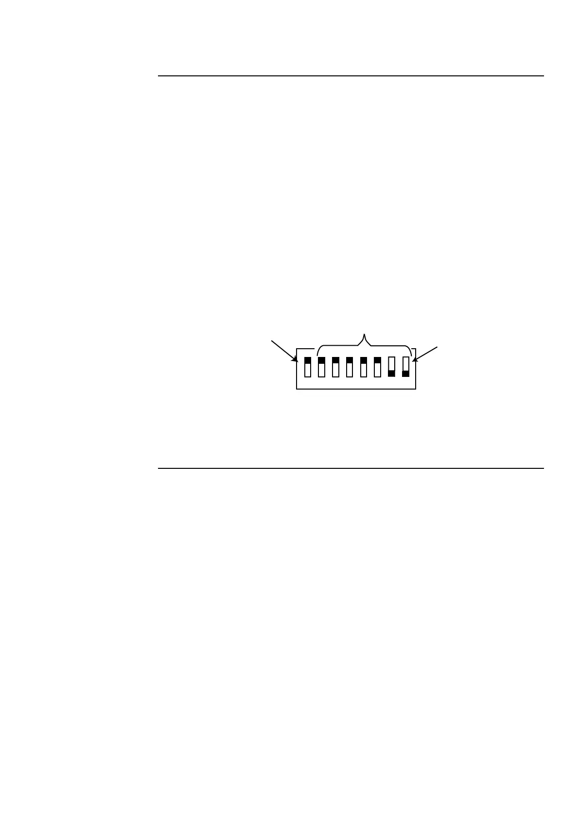
Figure 4. DIP Switch SW100
LT0638 Iss 1.1 7/2017 6
Use DIP Switches SW100-2 through
SW100-8 to set the Module Address.
This figure shows an Address of 3.
4100 Comm. Baud Switch
(SW100-1) must be set to ON
Position 8 is LSB
(least significant bit)
ON
OFF
OFF = ACTIVE
1 2 3 4 5 6 7 8
Programming
The MX Digital Loop Card is programed using the 4100ESi Programmer. Refer to
LT0619 4100ESi Programming Manual for details.