LT0432 Issue 1.04 13 October 2009 Page ii
Each of these diagrams shows the wiring for a particular module or card
or base which can be used with the AS4428.1 version of the Simplex
4100U Fire Alarm system.
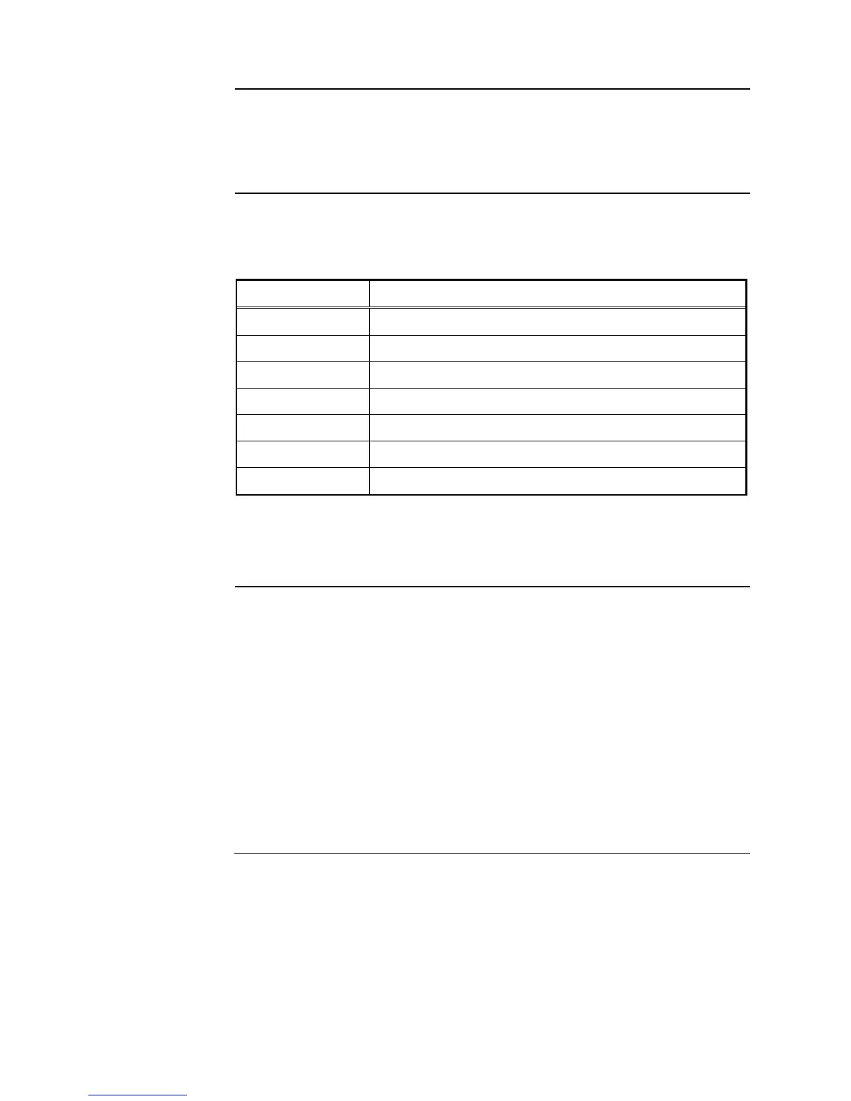
Each diagram has a 3 digit sheet number from the drawing series 1976-
181. This sheet numbering is divided into ranges, reflecting the type of
device or module, as follows:
Sheet Number Type of Devices Covered
100-199 Detectors & Bases
200-299 Zone Modules & Cards providing detection circuits
300-399 Input devices
400-499 Output devices or mixed inputs/outputs
500-599 Fault isolators
600-699 Communications – networks, printers, etc.
700-799 Power Supply details
The sheet index on the next page shows the current issue of each
diagram. The index also refers to some diagrams which have not been
released yet.
IDNet Individual Device Network – latest version of
addressable device communication.
MAPNET Multi-Application Peripheral Network – earlier version of
addressable device communication.
IAM Individually Addressable Module.
ZAM Zone Addressable Module – interfaces to conventional
detectors.
RUI Remote Unit Interface – connects Master panel and Slave
transponders.
RTU Remote Transponder Unit – slave panel
NAC Notification Appliance Circuit – drives DC-powered sounders
and visual warning devices.
General
Organisation
Amendment
Log
6 Oct. 2006
Issue 1.00 Original
20 Nov. 2006 Issue 1.01 Updated sheets 102, 203, 500
21 June 2007 Issue 1.02 Added sheet 205
10 July 2009 Issue 1.03 Updated sheet 413
13 Oct. 2009 Issue 1.04 Added sheets 701, 703, 704