EasyManua.ls Logo

Simplex SPS Series - User Manual

Simplex SPS Series
20 pages
Print Icon
To Next Page IconTo Next Page
Loading...
SPS/SKS SKID PUMP SET
PACKAGED PUMP SET
Question and Answer IconNeed help?

Do you have a question about the Simplex SPS Series and is the answer not in the manual?

Overview

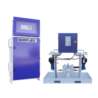
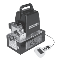
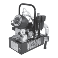
The Simplex SPS/SKS Skid Pump Set, also known as a Packaged Pump Set, is a pre-engineered, integrated system designed for fuel oil and lube oil transfer. These units are factory-assembled and include pumps, pump motors, controls, and accessories, all pre-plumbed and pre-wired within a weatherproof enclosure. The Packaged Pump Sets are suitable for wall or pad mounting, while the Skid Pump Sets, due to their open catch basin, are intended for indoor installation only.

Function Description:

The primary function of the Simplex Pump Set is to transfer fuel oil or lube oil (Class II or Class III combustible liquids with a flash point of 100°F or higher). The system is designed for reliability, utilizing job-engineered and system-matched components. It features isolated compartments for mechanical and electrical devices and external ports for field plumbing connections. A catch basin with a leak detector is integrated into the pump sets to enhance safety by detecting fuel line leaks.

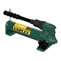
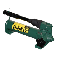
The pump sets are not self-priming and are shipped from the factory filled with #30 oil to aid in system priming. A hand pump, if equipped, can be used to lift fuel into the pump set cabinet, though manual priming at the pump is still necessary.

Usage Features:

  • Priming the System:

    • Ensure the pump is filled with #30 priming oil and all ball valves are open.
    • Use the hand pump to lift fuel to the fuel manifold level.
    • Open the pump inlet line or priming tee, fill with fuel, and then close the line. A foot valve in the main fuel tank is recommended to hold the fuel column.
    • If a fuel strainer is present, disassemble, fill with fuel, and reassemble it.
    • Energize the pump and observe fuel flow. In duplex systems, both pumps should be operated simultaneously during priming.
    • A vacuum gauge on the input side should read a maximum of 15" vacuum under normal conditions (equivalent to 20' vertical lift). Readings above 15" indicate excessive vertical lift or line restrictions.
    • A pressure gauge on the output side should read a minimum of 5 PSI and a maximum of 65 PSI under normal conditions. Readings above 65 PSI indicate excessive line restrictions or friction.
    • Pump Set flow switches have a 5 PSI minimum set point; pressure below this will trigger a loss of flow failure. Pressure relief valves are set at 65 PSI and will open to vent fuel back to the main storage tank if pressure exceeds this.
  • Single Pump Operation:

    • Apply control power and place the Main Disconnect Switch in the "On" position.
    • Automatic Mode: Place the Pump Selector Switch in "Auto." The pump starts when fuel contacts close and runs until they open.
    • Manual Mode: Place the Pump Selector Switch in "Manual." The pump motor runs until the switch is returned to "Off" or "Auto," or if the Overload Relay trips.
  • Duplex Pump Operation:

    • Designed for increased reliability with a backup pump and level control.
    • One pump is designated "lead" and the other "lag." The lead pump refills the tank from 50% to full.
    • If the fuel level drops below 50% (indicating lead pump failure or excessive consumption), the lag pump and its separate level controller activate, running alongside the lead pump until the tank is full.
    • To operate, apply control power and place the Main Disconnect Switch in "On."
  • Alternate Mode:

    • Place the Duplex Pump Mode Switch in "Alternate."
    • Pump #1 starts when fuel transfer contacts close and runs until they open.
    • Pump #2 starts when fuel transfer contacts close again and runs until they open.
    • Operation alternates between pumps with repeated calls for fuel transfer.
  • Both Run Mode:

    • Place the Duplex Pump Selector Switch in "Both."
    • Both pumps start when fuel transfer contacts close and run until they open.
    • No lead/lag alternation occurs in this mode.
  • Fuel Line Leak Detection:

    • If fuel is detected in the catch basin, a float switch closes, activating the fuel line leak alarm and illuminating the leak indicator.
    • A fuel line leak disables the fill pumps in "Auto" mode.
  • Loss of Flow Detection:

    • An adjustable time delay relay (set to 30 seconds by Simplex) is wired in parallel with the motor starter circuit via a normally closed flow switch. This allows time for the pump to establish flow and prevents false alarms.
    • If sufficient flow is not developed within 30 seconds or is lost during operation, the lag pump starts (in duplex systems), the failed pump stops, and the pump fail indicator lights up.
    • Alarm contacts are rated 10A @ 125/250VAC, 10A @ 30VDC.

Important Technical Specifications:

  • Fuel/Liquid Compatibility: Fuel oil, lube oil (Class II or Class III combustible liquids with a flash point of 100°F or higher). Not for use with gasoline or flammable liquids with a flash point less than 100°F.
  • Pump Type: Not self-priming.
  • Motor Rotation: Standard pump rotation is clockwise as viewed from the motor end. Incorrect wiring can reverse rotation and damage the pump shaft seal.
  • Pump/Motor Coupler Clearance: Approximately 1/8" clearance between coupler halves is required for proper alignment and to prevent excessive noise and wear.
  • Vacuum Gauge Readings: Max 15" vacuum (20' vertical lift) on the input side.
  • Pressure Gauge Readings: 5 PSI minimum to 65 PSI maximum on the output side.
  • Flow Switch Set Point: 5 PSI minimum.
  • Pressure Relief Valve Set Point: 65 PSI.
  • Alarm Contact Rating: 10A @ 125/250VAC, 10A @ 30VDC.

Maintenance Features:

  • Inspection Frequency: Every six months for light duty cycles; monthly for daily, long-hour usage.
  • Pre-Maintenance Safety: Ensure the main disconnect switch (if optional), user-supplied circuit breaker, and all power sources are OFF and isolated before maintenance.
  • Visual Inspection: Check the shipping crate and unit for damage upon arrival.
  • Mechanical Checks:
    • Check main disconnect switch, door, and hinge operation.
    • Check cabinet mounting hardware (feet and wall mounting flange) for tightness.
    • Check pump/motor hardware for tightness; double-nutted bolts should be checked.
    • Rotate the motor shaft by hand for smooth operation.
    • Check pump/motor coupler for proper alignment and spacing (1/8" clearance). Loosen mounting hardware to realign if necessary.
  • Electrical Checks:
    • Check all electrical terminals and connections for tightness.
    • Ensure proper grounding as shown in wiring diagrams to prevent fire and safety hazards.
  • Pump Testing (Duplex Systems): Test each pump individually, simultaneous operation, and alternating operation to ensure normal function.
  • Lubrication: All motors are permanently lubricated and do not require additional lubrication. Pumps are self-lubricating and do not require maintenance.
  • Plumbing Checks:
    • Check all plumbing joints for leaks and tighten fittings as necessary.
    • Drain accumulated fuel from the catch basin by removing the plug.
    • Inspect fuel strainers; disassemble, clean, and replace elements as needed. Reassemble and check for leaks.
    • Test hand pump operation and check for fuel leaks.

Simplex SPS Series Specifications

General IconGeneral
BrandSimplex
ModelSPS Series
CategoryWater Pump
LanguageEnglish

Related product manuals