SimpliFire • SF-BI30-E, SF-BI36-E • 2040-900 Rev. C • 2/13
24
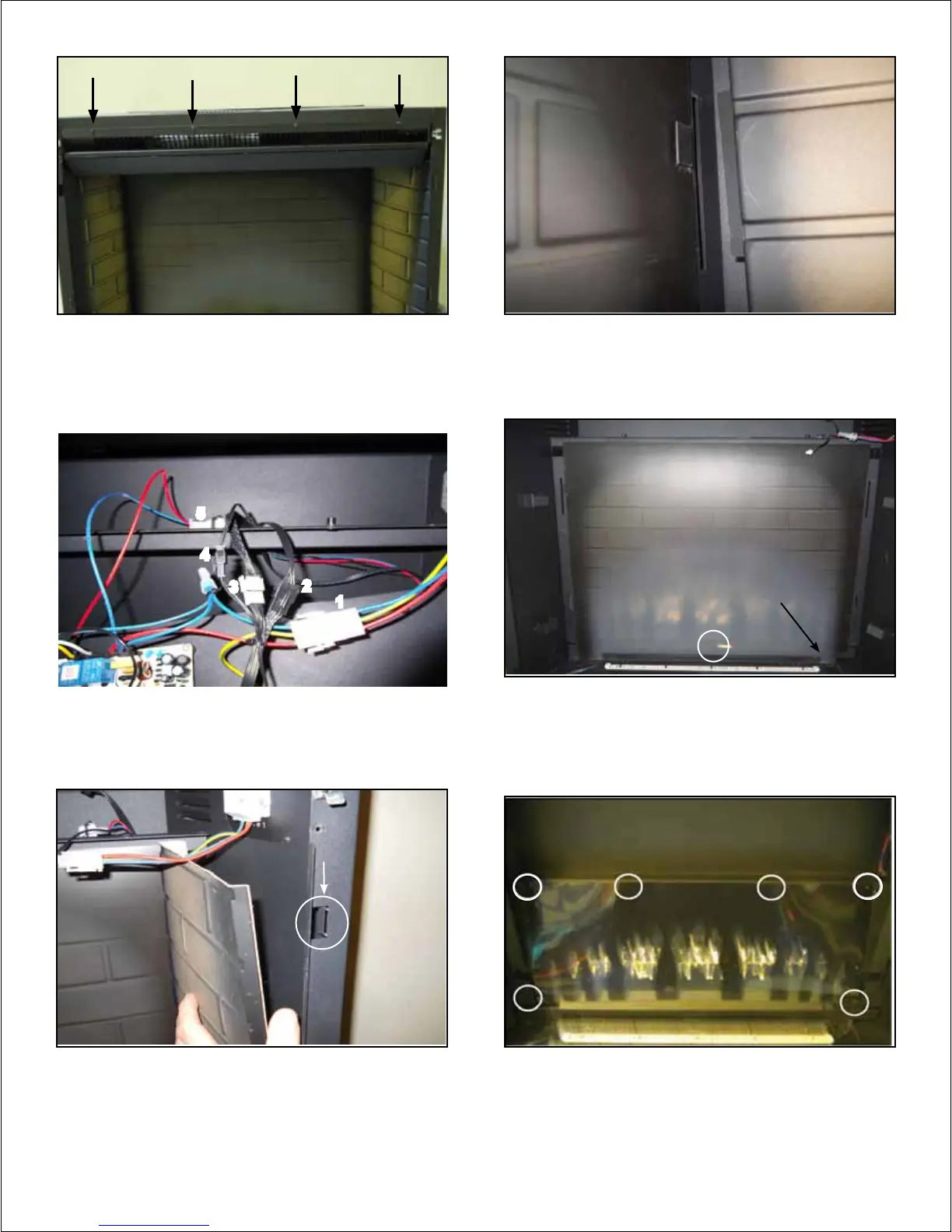
Figure 6.10 Five Electrical Connections required for Heater/
Blower Module Removal and Installation
Figure 6.11 Removal of Front Edge of Refractory from
Appliance Cavity
1
3
4
Figure 6.13 Location of one screw that retain Brick Panel to
Rear Wall of Appliance
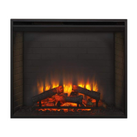
Figure 6.12 Alignment of Tabs in Rear Edge of Refractory with
Slots in Appliance
Figure 6.14 Location of four Screw Fasteners that attach
Flame Screen to Chassis
Note: Orientate so notch
is isolated on lower right
corner.
Front Edge
Retainer Tabs
5
2
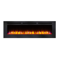
Figure 6.9 Four Screws that attach Blower/Heater Module to
Upper Face of Appliance