11
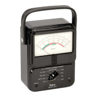
5. READING THE METER DIAL SCALES
The analog meter scales require interpolation to obtain readings that fall in be-
tween the major scale markings. See Figure 3 below, as example.
Figure 3
“+” and “W” Input Jacks
Connect the red (positive) test lead to the “+” jack and the black (ground) test lead
to the “W” jack.
“+” and “W” Output Jacks
Connect the positive and ground leads from a peak reading device to these jacks.
The Instrument output produces a scaled and buffered output voltage which
matches the waveform of the leakage current. At full scale meter deflection, the
output produces 1 volt RMS.
The output jack ground is tied to input jack ground. To avoid a “ground loop”
condition, which can cause false readings or Instrument damage, do not tie the
Instrument’s
output
ground jack to another ground.
Battery Compartment
Compartment houses the two (2) 9 volt NEDA type 1604A alkaline batteries and
input protection fuse. These are the only user serviceable parts in the Instrument.
Before opening the Instrument battery compartment, disconnect all test leads
and turn the power switch OFF.
6. SAFETY PRECAUTIONS
Although designed to ensure operator safety, this instrument measures poten-
tially fatal current and voltage levels. To guarantee safe operation, observe all
warnings and cautions contained in this manual and in the technical manuals of
the equipment under test.
!
!
1
.
0
1
.
5
2
.
0
1
0
0
40
60
Example: Burn hazard reading is 50mA RMS or
MIU (bottom) reading is 1.5 MIU for the 3 MIU range