13
7.2 Preparation
1. Turn power OFF to equipment under test.
2. If the meter pointer does not align with zero when Instrument power is OFF,
rotate the mechanical zero adjustment screw as necessary.
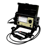
3. Connect the Instrument and equipment under test. Figure 4, above, shows a
typical test setup. Do not apply power.
4. Verify that proper line voltage is available for the equipment under test.
5. Turn the Instrument Power Switch to BATT. If pointer indicates satisfactory
battery condition, proceed with testing. If not, turn Instrument Power Switch to
OFF and replace the batteries before proceeding.
7.3 Voltage Measurement
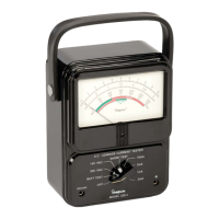
1. Turn the Instrument Power Switch to ON (see figure 5 below)
OUTPUT
REACT.
LET GO
228
3
10
1
3
ON
BATT.
OFF
+
5
0
.
5
.2
150
1
.
0
.
4
1
.
5
2.0
.
2
.
5
1
.
0
.
4
1
.
5
.6
.
6
2
.
0
.
8
2
.
5
2
0
0
1
.
0
3.0
2
.
5
.
8
3
.
5
1
.
2
4
.
0
1
.
4
2
5
0
3
0
0
V
O
L
T
S
R
.
M
.
S
MIU
PEAK
3
.
0
1
.
0
M
I
U
R
.
M
.
S
1
0
0
8
0
2
0
0
0
0
0
0
0
1
0
0
BATT.
OK
V
O
L
T
S
R
.
M
.
S
M
I
U
P
E
A
K
MIU
R.M
.S
4
0
6
0
B
U
R
N
H
A
Z
A
R
D
m
A
R
.
M
.
S
.
B
U
R
N
H
A
Z
A
R
D
m
A
R
.
M
.
S
.
WARNING
READ MANUAL BEFORE USE
!
+
RESPONSE
LEAKAGE CURRENT TESTER
BURN
HAZARD
(0-100µA)
SHOCK
HAZARD
(MIU)
VOLTS
DC-1KHz
300 Volts max
Appliance
Under Test
Grounded
Supply
Connector
SW 2
Open
Ground
SW1
+
_
120V
OUTPUT
REACT.
LET GO
228
VOLTS
ON
BATT.
OFF
+
WARNING
READ MANUAL BEFORE USE
!
+
LEAKAGE CURRENT TESTER
RESPONSE
DC-1KHz
300 Volts max
Figure 4. Typical Test Setup
Figure 5
2. Connect Instrument Test Leads to the input jacks — red lead to “+” and
black lead to “W”.