5
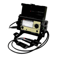
1. CONTROLS AND INDICATORS
1. Range Selector Switch for test voltage, battery test and power supply inter-
ruption
2. Range Key for measuring range selection
3.
indicator LED -green: valid measurement
-off: invalid measurement, battery too weak
4. Upper Range LED: indicates 1 T
scale is selected
5. Lower Range LED: indicates 100 M
scale is selected
6. Adjustor Screw for mechanical zero adjustment
7. Function Selector Switch for voltage or insulation resistance measurements
8. Analog Display
9. Test Probe Negative (-) Measurement Cable
10. Test Probe Positive (+) Measurement Cable
11. Guard Cable Connector Jack
12. Battery Module
2. SAFETY PRECAUTIONS
Simpson’s 505 Insulation Tester is manufactured and tested in accordance with
the following standards:
IEC 1010-1/EN 61010-1,
IEC 61557/EN 61557
In order to maintain flawless technical safety conditions and to assure safe use,
read the operating instructions carefully before using your instrument.
2.1 Repair and Parts Replacement
Voltage conducting parts may be exposed when the instrument is opened. The
instrument must be disconnected from all sources of voltage before repair or
replacement of parts. If the repair of an open, live instrument is unavoidable
instrument must be repaired by trained personnel who are familiar with the risks
involved.
SIMPSON ELECTRIC CO.
Lac Du Flambeau, WI 54538
w ww . . co m
information@itm.com1.800.561.8187