7
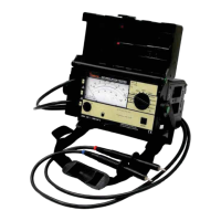
The tester is also equipped with a 2000 V measuring range for direct and alter-
nating voltages. This is especially advantageous for testing for the absence of
voltage, and for discharging of capacitive units under test.
4. INITIAL START-UP
4.1 Battery Installation
Before opening the battery compartment (side panel) be sure that the Function
Selector switch is set to the “V” position, and that the Range Selector switch is set
to the “OFF/V” position, and that the device is completely disconnected from all
external power circuits.
1. Unscrew and remove battery compartment.
2. Remove battery clip.
3. Pull battery holder out of battery compartment.
4. Insert six commercially available 1.5 V, 6.0 AH, “D” size batteries or storage
batteries (single cell) into battery holder with polarity as indicated by
symbols.
5. Push battery holder back into battery compartment.
6. Push battery clip back over contacts making certain that correct polarity
is assured.
7. Reinstall battery compartment to the housing in the correct direction (label-
ing must be legible) and fasten with screws.
4.2 Testing the Batteries
NOTE: If pointer only moves into minimal supply voltage range, several mea-
surements can still be performed for test voltages of less than 1000 V, because
the battery test is conducted with the same load as is used for a test voltage of
1000V.
4.3 Switching the Tester On and Off
As long as the Function Selector switch is set to and the Range Selector switch
is not in the OFF/ V position, tester remains activated. For transportation and
maintenance purposes, it is recommended that the Function Selector switch be
set to the V position, and the Range Selector switch be set to the OFF/ V position
in order to prevent unintentional activation.
NOTE: Be certain that the grip on the Function Selector switch points exactly to
“V” or “
”. This is especially important during discharging of capacitive devices
under test, because voltages are not displayed in intermediate selector switch
positions.
!
After batteries have been installed, or if indicator LED fails to light during
insulation resistance measurement, test batteries. For battery testing, the
Range Selector switch must briefly be set to the position. Deflection of pointer
on the analog dial within the scale during battery test indicates the condition of
batteries or storage batteries at an average load of 1000 V test voltage. The
position of the Function Selector switch will not affect battery test results. The left
end of the scale represents minimum required supply voltage, and the right end
represents maximum available supply voltage.
w ww . . co m
information@itm.com1.800.561.8187