8
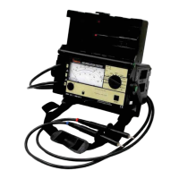
4.4 Analog Display
Logarithmic representation of the upper resistance scale allows for quick recog-
nition of the magnitude involved. In order to achieve the required accuracy for
testing of protective measures, the RANGE key allows for switching to the ex-
panded lower limit measuring range of 100 k
... 100 M . The orange colored
Upper Range and Lower Range LEDs, at the right end of the scale indicate
which of the two resistance measuring ranges is currently active.
The
indicator LED lights green to confirm correct insulation measurement. If
LED does not light, test voltage has not been achieved. If this happens test the
battery. The two lower scales are for battery testing and voltage measurement,
see paragraph 4.2 and 5 respectively.
5. DIRECT AND ALTERNATING VOLTAGE
MEASUREMENTS
Direct voltages and sinusoidal alternating voltages with frequencies ranging
from 15 to 500 Hz can be measured with the tester. Deflection of the pointer of the
instrument is always positive for direct voltage measurements, regardless of
polarity at the connections. Alternating voltage is indicated as an effective value.
Voltage measurements are used to test for the absence of voltage before insula-
tion resistance measurements, as well as for the automatic discharge of capaci-
tive devices under test. The voltage drop can be observed at the display.
NOTE: Regardless of the position of the Range Selector switch, voltage mea-
surement can always be performed with Function Selector switch in the “V” posi-
tion (even without batteries).
1. Set Function Selector switch to “V” position.
2. Check that pointer is at “0” in the V scale when the test probes are not
connected. Reset the pointer as required using Adjustor screw for mechani-
cal zero adjustment.
3. Position of Range selector switch has no influence on voltage measure-
ments, although we recommend setting it to the OFF/ V position.
4. Contact measuring points with both test probes.
5. Read measurement value at V scale.
NOTE: Voltages greater than 2000 V may not be applied. Input resistance for
voltage measuring
range is equal to 5 M
.
w ww . . co m
information@itm.com1.800.561.8187