2. Hysteresis: This is the percentage above or below the setpoint where the relay
actuates.
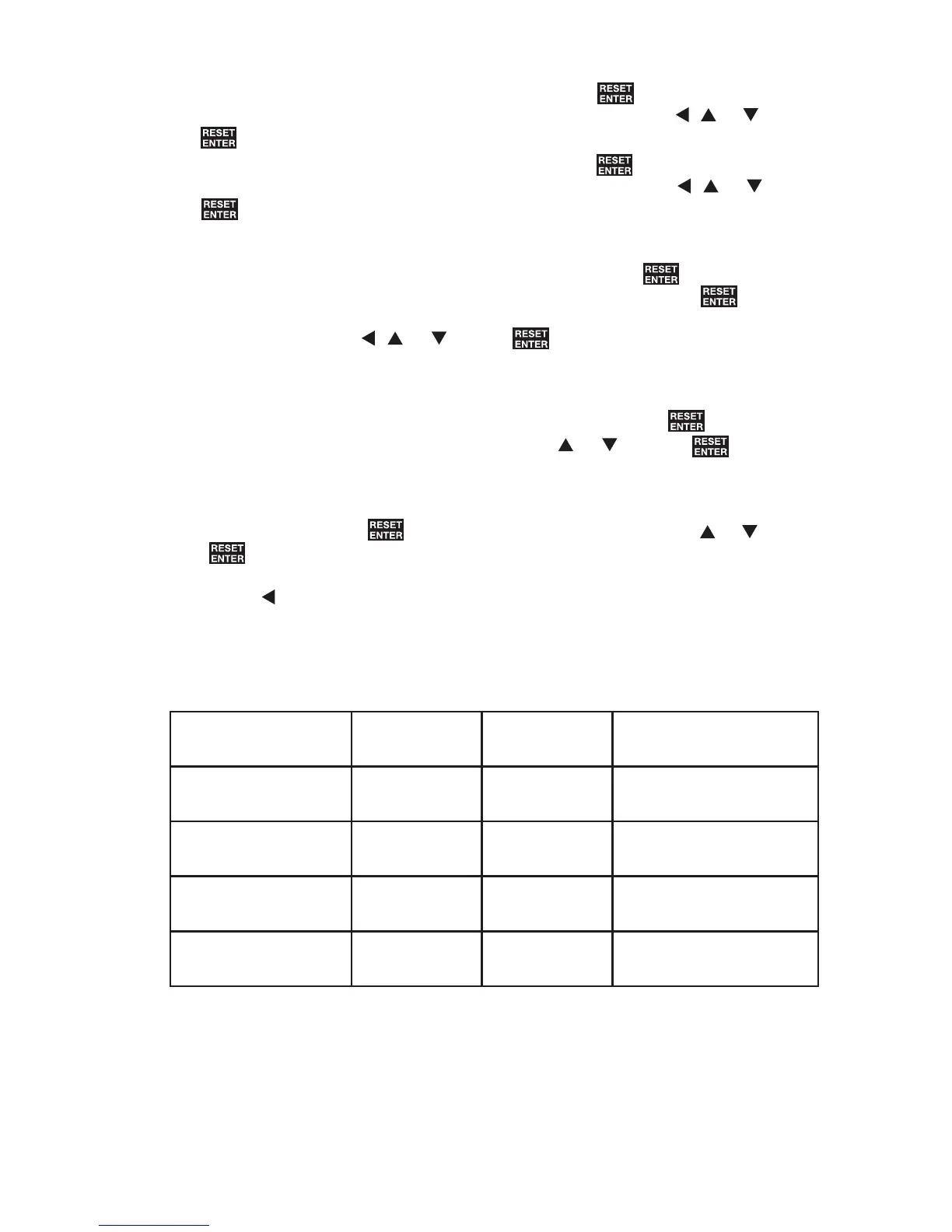
a. The display shows “
+B/R
” and a number. Press REs .
b. Enter the % of hysteresis (0-29.9%) falling Edge by using
, or . Press
REs .
c. The display shows “
+B+L
” and a number. Press REs .
d. Enter the % of hysteresis (0-29.9%) rising Edge by using
, or . Press
REs .
3. Latch: This parameter sets the given relay in activation even after the alarm
condition has been removed. To reset the relay press REs .
a. The display will flash between “
/W&+
” and a number. Press REs .
b. Enter the amount of delay desired before the relay actuates (0-60 Sec-
onds) by using
, or . Press REs .
4. Alarm: The unit now flashes alternately between “
$OU
” and “
+,
”. The alarm
condition can now be set to either above the setpoint (HI), below the setpoint
“
/R
” or “
R))
”. To set alarm to “
+,
”, “
/R
” or “
R))
”, press REs when display
flashes. Choose “
+,
”, “
/R
” or “
R))
” by using or . Press REs .
5. State: Choose the desired relay state, Normally Energized “
Q(
” or De-Ener
gized “
QG
” when the unit is not in alarm. The unit will flash alternately between
“
6W
” and “
QG
”. Press REs . Choose either “
Q(
” or “
QG
” by using or . Press
REs .
6. Press to return to main menu.
7. Set SP2, SP3 and SP4 as necessary and save changes.
Relay Card/State
and Alarm Settings Single Double Quad
De-Energized no
alarm
NC-Com
connected
NC-Com
connected
NO-Com disconnected
De-Energized in
alarm
NO-Com
connected
NO-Com
connected
NO-Com connected
Energized no alarm
NO-Com
connected
NO-Com
connected
NO-Com connected
Energized in alarm
NC-Com
connected
NC-Com
connected
NO-Com disconnected
Table 6-2
Relation between State, Alarm and Type of Relay Card Chart
This chart shows the relationship between the Alarm and State settings and the
type of relay card used.
NC = Normally closed terminal
NO = Normally opened terminal
Com = Common terminal
20