11 - ENG
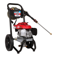
E. Quick-Connect Spray Wand: Allows the user to quickly change out
high pressure nozzles. See How To Use Spray Wand instructions in
Operationsection.
F. Detergent Tank: Feeds cleaning agents into the pump to mix with the
water. See How To Apply Chemicals/Cleaning Solvents instructions in
Operationsection.
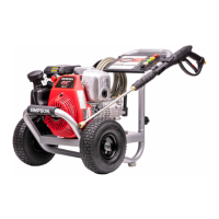
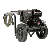
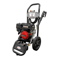
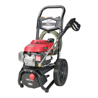
G. Handle
H. Frame
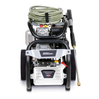
J. Pump Outlet
K. Pump Inlet
L. Quick Connect Nozzles
M. Nozzle Chart Label
N. Handle Knob
O. Spray Gun Holster
P. Thermal Relief (not shown)
Q. Filter Screen (not shown)
R. Trigger Lock (not shown)
S. Cleaning Tool (not shown)
T. Water Source (not shown)
BASIC ELEMENTS OF AN ENGINE
Refer to the Engine Owner's Manual for location and operation of enginecontrols.
Choke Control: Opens and closes carburetor chokevalve.
Starter Grip: Pulling starter grip operates recoil starter to crankengine.
Engine Switch: Enables and disables ignitionsystem.
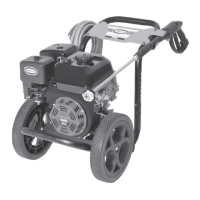
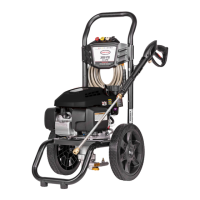
ASSEMBLY INSTRUCTIONS (FIG. 2–4)
1. Locate and remove all loose parts from thecarton.
2. Cut four corners of the carton from top to bottom and lay the panelsflat.
3. Place one hand on the handle (G) and one hand on the knob (N). Carefully pull
knob out and rotate the handle upward until it locks inplace.
NOTICE: Risk of personal injury. Avoid placing hands between handle and frame
when assembling to preventpinching.
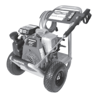
4. Mount the gun holster (O) to the upright frame tube using the saddle bolt and
knob provided.
FIG. 2
G
N
FIG. 2A
L
M
O