EasyManua.ls Logo

Simrad B&G NAC-3 - User Manual

Simrad B&G NAC-3
2 pages
To Next Page IconTo Next Page
Loading...
211.0 mm (8.31”)
195.0 mm (7.68”)
65.5 mm (2.58”)
92.0 mm (3.62”)
196.0 mm (7.72”)
Dimensions Mounting
Parts included
1. 1 x NAC™ -3 Autopilot Computer - IPX5
2. 4 x Fixing screws
3. 1 x Micro-C Drop cable (male) - 0.6 m
4. 1 x Micro-C T-Joiner
5. 7 x Connectors
6. 1 x 30 Amp fuse
7. Warranty card & literature pack
NAC
-3
INSTALLATION GUIDE
Trademark
®Reg. U.S. Pat. & Tm. O, and ™ common law marks.
Visit www.navico.com/intellectual-property to review
the global trademark rights for Navico Holding AS.
1
2
3
4
5
6
*988-11145-003*
For setup instructions, commissioning guide,
product manuals, technical specifications,
certificates and declarations,
refer to the product website:
www.simrad-yachting.com
www.bandg.com
System wiring example
AUTOPILOT
CONTROLLER
2
1
NMEA 2000® Backbone
Micro-C Drop cable
Micro-C Power cable
Micro-C T-Joiners
Micro-C Terminator, 120 Ohm
Rudder drive & Feedback cable
1
T T
MFD
12/24V DC
12/24V DC
12V DC
NAC-3
COMPASS
GPS
SENSOR
DRIVE UNIT
5
6
4
3
2
3
4
5
6
Power
NMEA 2000® Backbone
Micro-C Drop cable
Rudder Drive & Feedback cable
RUDDER
FEEDBACK
IPX5
Question and Answer IconNeed help?

Do you have a question about the Simrad B&G NAC-3 and is the answer not in the manual?

Simrad B&G NAC-3 Specifications

General IconGeneral
BrandSimrad
ModelB&G NAC-3
CategoryAutopilot System
LanguageEnglish

Summary

Installation Dimensions and Mounting

Unit Dimensions

Provides the physical dimensions of the NAC-3 unit in both millimeters and inches.

Mounting Requirements

Details the mounting specifications for the NAC-3 unit, including its IPX5 rating.

System Wiring and Components

System Wiring Example

Illustrates the typical system wiring connections for the NAC-3 autopilot configuration.

Included Parts List

Lists all components included in the NAC-3 Autopilot Computer installation kit.

Terminal Connections and Grounding

Terminal Layout and Access

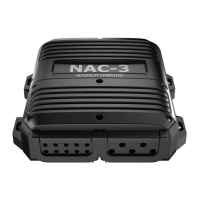
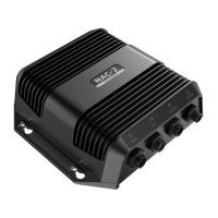
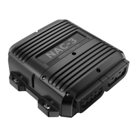
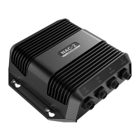
Details the layout of terminals on the NAC-3 unit and provides access information.

Grounding Procedure

Explains the correct grounding procedure for the NAC-3 unit to the vessel's main ground.

Power and Network Setup

Power Connection and Fuse Installation

Guides on connecting power, checking polarity, and installing the fuse for the NAC-3.

Network Connectivity

Describes how to connect the NAC-3 to the NMEA 2000® backbone.

Drive Unit and Mode Configuration

Drive Unit Connections

Details connections for various drive units: Reversible Pump, Hydraulic Linear, Rotary Drive.

Mode;Function Selector Options

Explains the functionality of Option 1 (Disengage Switch) and Option 2 (SteadySteer™).

External Interfaces and Feedback

External Alarm and NMEA 0183

Covers connections for external alarms and NMEA 0183 devices.

Rudder Feedback and External I;O

Details connections for rudder feedback sensors and external I/O signals.

Related product manuals